Download
1 / 38
380 likes | 770 Views
Transformer Training Board Power Supply. Advisor: Dr. Michael Mazzola Team Members: Gary Hutson, James Roberts, James Jackson, and Kenny Beverin. Team Members. Gary Hutson. James Roberts. James Jackson. Kenny Beverin. Team Responsibilities. Gary Hutson Web Designer Rectifier Circuit

E N D
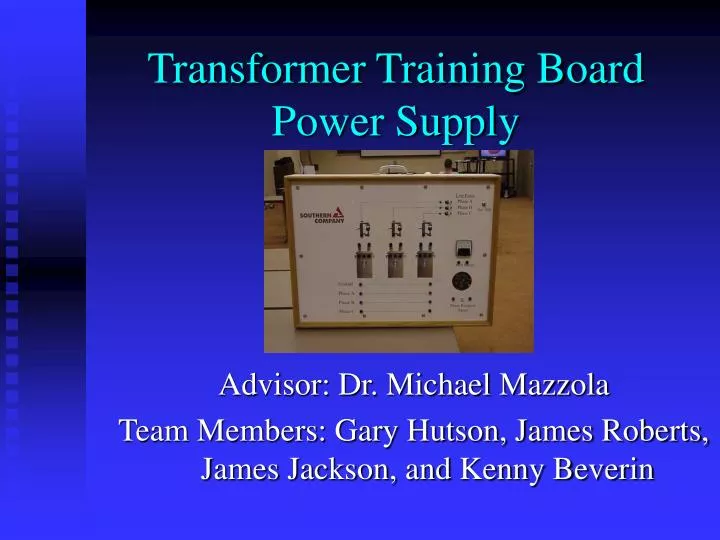
Transformer Training BoardPower Supply Advisor: Dr. Michael Mazzola Team Members: Gary Hutson, James Roberts, James Jackson, and Kenny Beverin
Team Members Gary Hutson James Roberts James Jackson Kenny Beverin
Team Responsibilities Gary Hutson Web Designer Rectifier Circuit DC-AC Inverter James Roberts Research DC-AC Inverter PSpice Kenny Beverin Stock Market Manager Executive Summary PWM Controller James Jackson Documentation References Design Requirements
Purpose To build a Power Supply that produces the desired output and is: • Light weight • Small • Durable • Quiet
Design Requirements • The 3-phase output voltage THD should be limited to 5%. • The phase to phase voltage should be limited to 43 volts +/- .5 volts • The weight limit is 20 pounds. • The size should be 12’’ cubed.
Rectifier (Simulated Unfiltered) Amplitude = 170V Average = 108V
DC Link Filter 10% Ripple Voltage Filter values: C = 91.7uF L = 109.6mH
Rectifier Output (Simulated Filtered) % Ripple Voltage = 7.35
Rectifier Output (Actual Filtered) Ripple Voltage = 12.6 V Peak Voltage = 165 V % Ripple Voltage = 7.64
DC to DC Converter • Input from Filter 170V DC unregulated • Regulated Outputs • - (+24VDC) Control Power • PWM Power • Phase Shifter • Function Generator • DC Bias Circuit • - (~90VDC) Inverter Power
Inverter • ~90VDC to 43VAC • 3-Phase Half Bridge Topology • Power MOSFETs • PWM Controlled
Controller Selection • Square Wave • Pulse-Width Modulation
Function Generator Symmetry adjuster • Supplies a Sinusoidal Reference signal • ~ 3 Volts peak to peak Amplitude adjuster Sine shape adjuster Resistor and capacitor for frequency adjust
Reference Signal Offset Signal from Function Generator PWM Expected Signal
DC Bias Circuit DC Bias Control
Phase Shifter (Simulated) Base signal - 0º Shifts signal -120º Shifts signal 120º
PWM Circuit Dead-time control resistors PWM pulses Timing capacitor and resistor to determine switching frequency
PWM Isolation An Isolation Relay will be used to isolate the PWM circuit from the Inverter Bridge
Low Pass Filter and Load C = 1.5uF Low Pass Filter Artificial Load
Future Plans • Improve THD • Obtain desired Voltage • Package the product • Provide protection from over current • Provide thermal protection
Acknowledgements • Dr. Mazzola for his continued support • Robert Cheney from Alabama Power • Roger D. Marcus from Alabama Power
Demo • The Unfiltered DC Voltage • Filtered DC Voltage • Function Generator • Phase Shifter • PWM Pulses and Control signal • Output
References [1] I. M.Gottlieb, Electronic Power Control, TAB Books, Blue Ridge Summit, PA, USA, 1991. [2] B. Jayant Baliga, Modern Power Devices, John Wiley & Sons, New York, New York, USA, 1987. [3] N. Mohan, Tore M. Undeland, and William P. Robbins, Power Electronics: Converters, Applications, and Design, John Wiley & Sons, New York, New York, USA, 1989. [4] I. M. Gottlieb, Power Control with Solid State Devices, Reston Publishing Company, Inc., Reston, Virginia, USA, 1985. [5] B. Norris, Microprocessors and Microcomputers and Switching Mode Power Supplies, McGraw-Hill Book Company, New York, New York, USA, 1978. [6] B.W. Williams, Power Electronics: Devices, Drivers, and Applications, John Wiley & Sons, New York, New York, USA, 1987. [7] B. K. Bose, Microcomputer Control of Power Electronics and Drives, IEEE Press, New York, New York, USA, 1987. [8] K. Shenai, “Made-To-Order Power Electronics,” IEEE Spectrum, pp. 50-55, July 2000. [9] R. Neale, “’Tiny Switch’ Offers The Main Plug Integrated Power Supply,” Electronic Engineering, pp. 51-52, October 1998.
References (cont.) [10] B. Lin and H. Lu, “Single-Phase Three-Level Rectifier and Random PWM Inverter Drives,” IEEE Transactions on Aerospace and Electronic Systems, vol. 35, no. 4, pp. 1334-1343, October 1999. [11] H. Park, S. Park, J. Park, and C. Kim, “A Novel High-Performance Voltage Regulator for Single-Phase AC Sources,“ IEEE Transactions on Industrial Electronics, vol. 48, no. 3, pp. 554-562, June 2001. [12] C. Lin and C. Chen, “Single-Wire Current-Share Paralleling of Current-Mode- Controlled DC Power Supplies,“ IEEE Transactions on Industrial Electronics, vol. 47, no. 4, pp. 780-786, August 2000. [13] B. Lin, “Analysis and Implementation of a Three-Level PWM Rectifier/Inverter,“ IEEE Transactions on Aerospace and Electronic Systems, vol. 36, no. 3, pp. 948-956, July 2000. [14] J. Ghijselen, A. Vanden Bossche, and J. Melkebeek, “Dynamic Control of a Fixed Pattern Rectifier,“ IEEE Transactions on Power Electronics, vol. 16, no. 1, pp. 118-124, January 2001.
References (cont.) [15] I. Schmidt, “Secure Power Supply System With Static Power Converters,” IEEE 1977 Int’l Semiconductor Power Conversion, pp. 222-223, Lake Buena Vista, Florida, USA, March 1977. [16] K. Ishimatsu, “A DC-AC converter, using A Voltage Educational Type Switched-Capacitor Transformer,” IEEE 13th Applied Power Electronics Conference, pp. 603-606, Anaheim, California, USA, February 1998. [17] R. W. Stokes, “High Voltage Transistor Inverters For A.C. Traction Drives,” IEEE 1977 Int’L Semiconductor Power Conversion, pp. 270-294, Lake Buena Vista, Florida, USA, March 1977. [18] N. Mohan, T. Undeland, and W. Robbins, Power Electronics, Hemilton Printing Company, New York, New York, USA. 1995. [19] K. Ross, “V68HC912B32 PWM Module”,http://www.seattlerobotics.org/ encoder/apr98/68hc12pwm.html, Encoder, The Newsletter of the Seattle Robotics Society, Seattle, Washington, USA, April 1998. [20] “Frequency Converter Overview”, http://www.majorpower.com/frequency/ overview.html, Majorpower.com, Champlain, New York, USA.