Download
1 / 64
650 likes | 921 Views
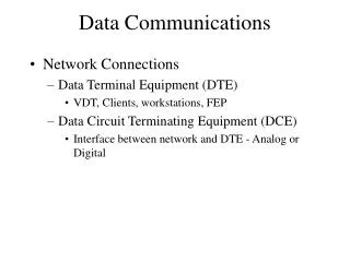
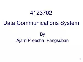
4123702 Data Communications System. By Ajarn Preecha Pangsuban. Chapter 4 – Digital Transmission. Digital Transmission. Methods to transmit data digitally Line coding Block coding Sampling Transmission modes Parallel Serial Synchronous Asynchronous. Digital Signals.

E N D
4123702Data Communications System By Ajarn Preecha Pangsuban
Digital Transmission • Methods to transmit data digitally • Line coding • Block coding • Sampling • Transmission modes • Parallel • Serial • Synchronous • Asynchronous 4123702 Data Communications System @YRU
Digital Signals • Digital – have a limited number of defined values • Use binary (0s and 1s) to encode information • Less affected by interference (noise); fewer errors 4123702 Data Communications System @YRU
4.1 Line Coding • Process of converting binary data to a digital signal 4123702 Data Communications System @YRU
Line Coding Characteristics • Signal Level versus Data Level • Pulse Rate versus Bit Rate • DC Components • Self-Synchronization 4123702 Data Communications System @YRU
Signal Level versus Data Level • Signal level – number of different values allowed in a signal • Data level – number of symbols used to represent data b.Three signal levels, two data levels 4123702 Data Communications System @YRU
Pulse Rate versus Bit Rate • Pulse rate – defines number of pulses per second • Pulse – minimum amount of time required to transmit a symbol • Bit rate – defines number of bits per second Bit rate = Pulse rate × log 2L When L is the number of data level of the signal 4123702 Data Communications System @YRU
Pulse Rate = = 1000 pulses/s Bit Rate = Pulse Rate × log2 L = 1000 × log2 2 = 1000 bps Example 1 A signal has two data levels with a pulse duration of 1 ms. We calculate the pulse rate and bit rate as follows: 4123702 Data Communications System @YRU
Pulse Rate = = 1000 pulses/s Bit Rate = Pulse Rate × log2 L = 1000 × log2 4 = 2000 bps Example 2 A signal has four data levels with a pulse duration of 1 ms. We calculate the pulse rate and bit rate as follows: 4123702 Data Communications System @YRU
DC Components • Residual direct-current (dc) components or zero frequencies are undesirable • Some systems do not allow passage of a dc component (such as a transformer); may distort the signal and create output errors • DC component is extra energy residing on the line and is useless 4123702 Data Communications System @YRU
DC Component 4123702 Data Communications System @YRU
Self-Synchronization • Digital signal includes timing information in the data being transmitted to prevent misinterpretation Figure 4.16 Lack of synchronization 4123702 Data Communications System @YRU
Example 3 In a digital transmission, the receiver clock is 0.1 percent faster than the sender clock. How many extra bits per second does the receiver receive if the data rate is 1 Kbps? How many if the data rate is 1 Mbps? Solution At 1 Kbps: 1000 bits sent 1001 bits received1 extra bps At 1 Mbps: 1,000,000 bits sent 1,001,000 bits received1000 extra bps 4123702 Data Communications System @YRU
Line Coding Schemes 4123702 Data Communications System @YRU
Unipolar • Simplest method; inexpensive • Uses only one voltage level • Polarity (+ or -) is usually assigned to binary 1; a 0 is represented by zero voltage 4123702 Data Communications System @YRU
Unipolar • Potential problems: • DC component • Lack of synchronization 4123702 Data Communications System @YRU
Polar • Uses two voltage levels, one positive and one negative • Alleviates DC component • Variations • Nonreturn to zero (NRZ) • Return to zero (RZ) • Manchester • Differential Manchester 4123702 Data Communications System @YRU
Nonreturn to Zero (NRZ) • Value of signal is always positive or negative • NRZ-L (NRZ-Level) • Signal level depends on bit represented; positive usually means 0, negative usually means 1 • Problem : synchronization of long streams of 0s or 1s • NRZ-I (NRZ-Invert) • Inversion of voltage represents a 1 bit • 0 bit represented by no change • Allows for synchronization 4123702 Data Communications System @YRU
NRZ-L and NRZ-I Encoding 4123702 Data Communications System @YRU
Return to Zero (RZ) • In NRZ-I, long strings of 0s may still be a problem • May include synchronization as part of the signal for both 1s and 0s • How? • Must include a signal change during each bit • Uses three values: positive, negative, and zero • 1 bit represented by positive-to-zero • 0 bit represented by negative-to-zero 4123702 Data Communications System @YRU
RZ Encoding 4123702 Data Communications System @YRU
RZ Encoding • Disadvantage • Requires two signal changes to encode each bit; more bandwidth necessary 4123702 Data Communications System @YRU
Manchester • Uses an inversion at the middle of each bit interval for both synchronization and bit representation • Negative-to-positive represents binary 1 • Positive-to-negative represents binary 0 • Achieves same level of synchronization with only two levels of amplitude 4123702 Data Communications System @YRU
Manchester Encoding 4123702 Data Communications System @YRU
Differential Manchester • Inversion at middle of bit interval is used for synchronization • Presence or absence of additional transition at beginning of interval identifies the bit • Transition means binary 0; no transition means 1 • Requires two signal changes to represent binary 0 but only one to represent 1 4123702 Data Communications System @YRU
Differential Manchester 4123702 Data Communications System @YRU
Bipolar Encoding • Uses three voltage levels: positive, negative, and zero • Zero level represents binary 0; 1s are represented with alternating positive and negative voltages, even when the 1 bits are not consecutive • Two schemes • Alternate mark inversion (AMI) • Bipolar n-zero substitution (BnZS) 4123702 Data Communications System @YRU
Bipolar AMI • Neutral, zero voltage represents binary 0 • Binary 1s represented by alternating positive and negative voltages 4123702 Data Communications System @YRU
Bipolar n-zero substitution (BnZS) • Solves problem of synchronizing sequential 0s, often occurring in long-distance transmission • If n consecutive zeros occur, some of the bits in those n bits become positive or negative • Substitution violates rules of AMI in a manner that receiver knows the bits are actually 0s and not 1s 4123702 Data Communications System @YRU
Other Schemes • 2B1Q (two binary, one quaternary) uses four voltage levels • One pulse can represent 2 bits; more efficient 4123702 Data Communications System @YRU
Other Schemes • MLT-3 (multi-line transmission, three level) – similar to NRZ-I using three levels of signals; signal transitions occur at beginning of 1 bit, no transition at beginning of 0 4123702 Data Communications System @YRU
4.2 Block Coding • Coding method to ensure synchronization and detection of errors • Three steps: division, substitution, and line coding 4123702 Data Communications System @YRU
Step 1 Step 2 Step 3 Steps in Transformation 4123702 Data Communications System @YRU
Transformation Steps • Step 1: bit stream is divided into groups of m bits • Step 2: substitute an m-bit code for an n-bit group • Codes with no more than three consecutive 0s or 1s are used to achieve synchronization • Since only a subset of blocks are used, if one or more bits are changed and an invalid code is received, a receiver can easily detect the error • Step 3: line encoding scheme is then used to create the signal 4123702 Data Communications System @YRU
Common Block Codes • 4B/5B – every 4 bits of data is encoded into a 5-bit code; NRZ-1 is usually used for line coding • 8B/10B – group of 8 bits of data is substituted by a 10-bit code • 8B/6T – each 8-bit group is substituted with a six-symbol code; uses less bandwidth since three signal levels may be used 4123702 Data Communications System @YRU
Figure 4.16 Substitution in block coding 4123702 Data Communications System @YRU
Table 4.1 4B/5B encoding 4123702 Data Communications System @YRU
Table 4.1 4B/5B encoding (Continued) 4123702 Data Communications System @YRU
Figure 4.17 Example of 8B/6T encoding 4123702 Data Communications System @YRU
4.3 Sampling • Analog data must often be converted to digital format (ex: long-distance services, audio) • Sampling is process of obtaining amplitudes of a signal at regular intervals 4123702 Data Communications System @YRU
Pulse Amplitude Modulation (PAM) • Analog signal’s amplitude is sampled at regular intervals; result is a series of pulses based on the sampled data • Pulse Coded Modulation (PCM) is then used to make the signal digital 4123702 Data Communications System @YRU
Note: Pulse amplitude modulation has some applications, but it is not used by itself in data communication. However, it is the first step in another very popular conversion method called pulse code modulation. 4123702 Data Communications System @YRU
Pulse Coded Modulation (PCM) • First quantizes PAM pulses; an integral value in a specific range to sampled instances is assigned • Each value is then translated to its 7-bit binary equivalent • Binary digits are transformed into a digital signal using line coding 4123702 Data Communications System @YRU
Figure 4.19 Quantized PAM signal 4123702 Data Communications System @YRU
Figure 4.20 Quantizing by using sign and magnitude 4123702 Data Communications System @YRU
Figure 4.21 PCM 4123702 Data Communications System @YRU
Digitization of an Analog Signal 4123702 Data Communications System @YRU
Sampling Rate: Nyquist Theorem • Accuracy of digital reproduction of a signal depends on number of samples • Nyquist theorem: number of samples needed to adequately represent an analog signal is equal to twice the highest frequency of the original signal 4123702 Data Communications System @YRU
Note: According to the Nyquist theorem, the sampling rate must be at least 2 times the highest frequency. 4123702 Data Communications System @YRU