Download
1 / 62
1.06k likes | 1.85k Views
DESIGNING OF A SMALL WEARABLE CONFORMAL PHASED ARRAY ANTENNA FOR WIRELESS COMMUNICATIONS. By Sayan Roy Major Advisor: Dr. Benjamin D. Braaten Dept. of ECE, NDSU, Fargo, ND, USA. Contents. Introduction Defining the Problem Phased Array Antenna Realization of Conformal Phased Array Antenna

E N D
DESIGNING OF A SMALL WEARABLE CONFORMAL PHASED ARRAY ANTENNA FOR WIRELESS COMMUNICATIONS By Sayan Roy Major Advisor: Dr. Benjamin D. Braaten Dept. of ECE, NDSU, Fargo, ND, USA
Contents • Introduction • Defining the Problem • Phased Array Antenna • Realization of Conformal Phased Array Antenna • Designing of Phased Array Antenna Test Platform • Scanning Properties of Phased Array Antenna Test Platform • Four Element SELFLEX Array Design • Scanning Properties of SELFLEX Array • Conclusion
Introduction to Array Antenna Conformal Antenna Phased Array Antenna
Antenna • For any communication device, an antenna system serves the purpose for external communication wirelessly.
Array Antenna • Array means a collection of similar entities. • Array Antenna • Set of individual antenna elements connected together to behave as a single unit • Advantages • Higher Gain • Beam Steering Capability • Reliable • Higher SNR
Beam Steering • In any Antenna system, the transmitting or receiving signal has two attributes: • Amplitude (A) and • Phase (φ). • Beam Steering can be achieved in an array antenna by changing the progressive phase differences between antenna elements. Beam steered 45° from Broadside direction
Conformality • Conformality can be described as a map projection which has the property of preserving relative angles over small scales. • In Mathematics, a conformal map is a function which preserves angles.
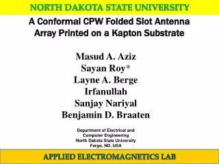
Conformal Antennas • Often mechanical design of a communication system requires that the associated antenna should be mounted on a curved surface. • Applications • Aerospace Designs • Wearable Antenna • Spacesuit • Mobile Devices • For last couple of years, designers have been showing interest in simulating conformal antenna performance to optimize antenna parameters in presence of conformal surface.
Relation between Conformality and Beam Steering • A conformal surface changes its curvature with time and may be planar or non-planar. • When an antenna system lies on a planar conformal surface, the field pattern of the antenna behaves normally.
Relation between Conformality and Beam Steering (cont.) • However, when the surface of the antenna becomes non-planar, the performance of the antenna starts to degrade.
Relation between Conformality and Beam Steering (cont.) • Beam Steering concept can be implemented to recover the field pattern of the antenna system by proper correction in relative phases between elements of the array. • This type of antenna is known as Phased Array Antenna.
Defining the Problem:Can we recover the radiation pattern of a conformal array ?
Phased Array Antenna Defining Co-ordinate Theory of Array Factor Concept of Phase Scanning Phase Compensation Technique of a Conformal Array Antenna
Defining Co-ordinate • (θ,φ) is the direction in space
Array Factor (AF) • The array factor due to isotropic point sources is the weighted sum of the signals received by the elements. • Mathematically, where N = number of elements is the complex weight for element n k=2π/λis the wave number (xn, yn, zn) is the location of element n
Array Factor (AF) (cont.) • Unique for each array • Depends on • number of elements, • relative magnitude and phase of current on each element, • relative inter-element spacing and • geometrical orientation of the elements. • Use • Pattern Multiplication Rule • If the response of a single element of a linear array is then the total response of the arraytotalcan be written as, total
Concept of Phase Scanning • Phase Scanning Circuitry • Why? • Electronic Beam Steering • Technique • Time Delay Scanning • Frequency Scanning • Phase Scanning • Why Phase Scanning? • Ease of Implementation • Cheaper Digital Control Circuitry • Fast Response Time • High Sensitivity
Concept of Phase Scanning (cont.) • How? • By controlling the progressive phase difference between each individual elements of an array. • Implementation • Diode Phase Shifter • Ferrite Phase Shifter • Industrial Solution • Digitally controlled fixed step phase shifter • Analog controlled continuous phase shifter
Phase Scanning Technique • Implementation • Series Phasers • Advantage: • Sharing Equal Power • Disadvantages: • Unequal Inter-element Phase Shift, so complex control circuitry. • Summed up Attenuation • Parallel Phasers • Advantages: • Phase Shifters act independently • Simpler Control Circuit • Disadvantage: • Each phase shifter does not share equal power • Example • Switched Line Phase Shifter • Ferrite Phase Shifter
Conformal Antenna-Challenges and Solution • Challenges • For a conformal antenna, the surface of the substrate changes with time during operation. • When the surface remains planar, the antenna behaves normally. • However for non-planar orientation, the radiation pattern gets distorted. • Solution • By applying the concept of phase steering, correct radiation pattern can be recovered.
Realization of Conformal Phased Array AntennaEquation for Phase CorrectionProposed System Block
Determining possible conformal surfaces in terms of application Conformal Antennas are used basically as wearable antennas which may be shaped as wedge or cylindrical in non-planar orientation.
A linear conformal array antenna placed on a Wedge shaped surface
A linear conformal array antenna placed on a Cylindrical surface
Equation for Phase Correction • An x- and z- translation is incurred from the original flat position for each array element. • Fields arriving at the reference plane associated with A±2 lagged from fields arriving at the reference plane associated with A±1. • So, the phases of current at A±2 should be positive enough to compensate the phase delay by that free space propagation to maintain equivalent planar orientation. • As the phase has being corrected towards the source, the phase correction will be additive in nature. • For wedge shaped surface, this correction can be achieved by introducing phase to each element where • For cylindrical surface, this correction can be achieved by introducing phase to each element where
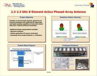
4-element antenna array with connectors • g=2.0 mm, h=35.6 mm, t=1.3 mm w=43.6 mm. • Rogers 6002(εr=2.94) 60 mil substrate. • Resonant Frequency: 2.46 GHz
Four port Receiver RF Circuit Board • Consists of • Voltage controlled Analog Phase Shifters • Voltage Controlled Attenuators • Amplifier and • Power Combiner • Industry Available • Each component was tested and verified prior to application with single prototype
Four port Receiver RF Circuit Board (cont.) • Multiple Input Single Output System • RT/duroid 6002 60 mil (εr=2.94) • Controlled by DAC Circuit through LabVIEW GUI
DAC Circuit • 12 bit, octal, 64 pin, low power DAC • Output ranges from 0V to 33 V for unipolar operation • Allows programmable gain of x4 or x6 w.r.t the applied reference voltage • Features Serial Peripheral Interface that can be operated at 50 MHz and is logic compatible with 1.8V, 3V or 5V • The register consists of a R/W bit, 5 address bits and 12 data bits • Operated in both synchronous and asynchronous mode • TQFP(Thin Quad Flat Package)-64 (10 x 10mm) used
LabVIEW GUI • National Instrument LabVIEW USB 6008 peripheral device was used to communicate with the GUI • 4 phase shifters and 4 attenuators can be controlled by 8 separate output channels from DAC with precision up to 300 mV
Phase Compensation Calculation • The expression for Array Factor can be redefined in Spherical coordinate as: where θsis the elevation steering angle Φsis the elevation steering angle A is the amplitude to each element Element factor and Then the compensated Array Factor () will be
Gain Calculation • The primary objective through this correction is to recover the gain. • If the reference gain of the system for a particular orientation is Gr(θ,Φ) and the compensated gain after the correction is Gc(θ,Φ),then for ideal condition Gr (θ,Φ) = Gc(θ,Φ) • However, the projected spacing between the elements deviates from λ/2 value for any non-planar orientation. • Due to this geometrical limitation, compensated gain can never be achieved to be equal to the reference gain. This gain shift (Gs) has been measured for all conformal cases and compared with analytical result.
Gain Calculation (cont.) Gs(θ,Φ) = Gc(θ,Φ) - Gr(θ,Φ)
Test Platform Results • Advantages • Practically validates the theory of beam steering • Ability of recovering the radiation pattern has been demonstrated for a general array • Gain Calculation has been presented showing low loss of gain • Disadvantages • Manual control required for any changes of conformal surface • The array was formed by individual element with separate feeding points. But an array should be acting as an individual element. • Gain shift
SELFLEX Array Design • Challenges • Can we design a conformal array on a single substrate with phase correction capability? • Can we achieve radiation pattern recovery for a conformal array in an autonomous manner? • Can we reduce the gain shift? • Solution • By designing a SELFLEX (SELF-adapting FLEXible) array antenna.