Download
1 / 14
140 likes | 305 Views
Microprocessor Lattice Mico 32. Presented by SADAF BAIG. Features. RISC architecture. 32-bit data path. 32-bit instructions. 32 general purpose registers. up to 32 external interrupts. 32 bits for address 8k Caches (i) instruction cache (ii) data cache

E N D
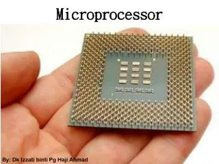
MicroprocessorLattice Mico 32 Presented by SADAF BAIG
Features • RISC architecture. • 32-bit data path. • 32-bit instructions. • 32 general purpose registers. • up to 32 external interrupts. • 32 bits for address • 8k Caches (i) instruction cache (ii) data cache • Configurable instruction set including user defined instructions. • Optional pipelined memories. • Dual memory interfaces.(instruction and data) • Memory mapped I/O. • 6 stage pipeline.
Tool chain • GCC - C/C++ compiler. • Binutils - Assembler, linker and binary utilities. • GDB - Debugger. • Eclipse - IDE. • Newlib - C library. • uCos-II, uITRON, RTEMs - RTOS. • uCLinux - O/S.
Peripheral Components • • Memory controllers • DDR & DDR2 SDRAM controllers • SPI Flash ROM • Asynchronous SRAM • On-chip block memory • • I/O • 32-bit timer • Tri-Speed Ethernet MAC • DMA controller • Master controller
General purpose registers • r0 Holds the value zero • r1 General-purpose/argument 0/return value 0 Caller • r2 General-purpose/argument 1/return value 1 Caller • r3 General-purpose/argument 2 Caller • r4 General-purpose/argument 3 Caller • r5 General-purpose/argument 4 Caller • r6 General-purpose/argument 5 Caller • r7 General-purpose/argument 6 Caller • r8 General-purpose/argument 7 Caller • r9 General-purpose Caller
General purpose registers • r10 General-purpose Caller • r11 General-purpose Callee • r12 General-purpose Callee • r13 General-purpose Callee • r14 General-purpose Callee • r15 General-purpose Callee • r16 General-purpose Callee • r17 General-purpose Callee • r18 General-purpose Callee • r19 General-purpose Callee • r20 General-purpose Callee • r21 General-purpose Callee • r22 General-purpose Callee • r23 General-purpose Callee • r24 General-purpose Callee • r25 General-purpose Callee • r26/gp General-purpose/global pointer Callee
Control and Status register • r27/fp General-purpose/frame pointer Callee • r28/sp Stack pointer Callee • r29/ra General-purpose/return address Caller • r30/ea Exception address • r31/ba Breakpoint address
Interrupts • IE – Interrupt Enable • The IE CSR contains a single-bit flag, IE, that determines whether interrupts are enabled. This flag has priority over the IM CSR. In addition, there are two bits, BIE and EIE, that are used to save the value of the IE field. • IM – Interrupt Mask • The IM CSR contains an enable bit for each of the 32 interrupts. Bit 0 corresponds to interrupt 0. In order for an interrupt to be raised, both an enable bit in this register and the IE flag in the IE CSR must be set to 1. After reset, the value of the IM CSR is h00000000.
Interrupts • IP – Interrupt Pending • The IP CSR contains a pending bit for each of the 32 interrupts. A pending bit is set when the corresponding interrupt request line is asserted low. Bit 0 corresponds to interrupt 0.After reset, the value of the IP CSR is h00000000.
32 bit micro controller 32-bit data path. 32-bit instructions. 32 general purpose registers. up to 32 external interrupts. 32 bits for address 32 bit program counter 8 bit microcontroller 8-bit data type. 128B of RAM 4kB on chip ROM 6 interrupt sources 4 I/O ports Address upto 64kB 16 bit program counter Comparison between lattice mico and 8051
32 bit micro controller 32-bit data path. 32-bit instructions. 32 general purpose registers. up to 32 external interrupts. 32 bits for address 32 bit program counter 16 bit for address 256B of RAM 4kB on chip ROM 16 bit program counter 16 bit stack pointer 52 pins Buses are multiplexed 5 addressing modes Comparison between lattice mico and HC11
Applications • The LatticeMico32 provides the performance and flexibility suitable for a wide variety of • markets • Communications • consumer • computer • medical • industrial • automotive.