Download
1 / 18
180 likes | 341 Views
Integrated test environment for a part of the LHCb calorimeter. TWEPP 2009 Carlos Abellan Beteta La Salle, URL. Integrated test environment for a part of the LHCb calorimeter. Presentation Outline Introduction Real environment Former test boards Final test board Test capabilities

E N D
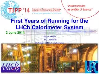
Integrated test environment for a part of the LHCb calorimeter TWEPP 2009 Carlos AbellanBeteta La Salle, URL TWEPP09 Parallel session B2a - Production, testing and reliability
Integrated test environment for a part of the LHCb calorimeter Presentation Outline • Introduction • Real environment • Former test boards • Final test board • Test capabilities • Features • Conclusions Parallel session B2a - Production, testing and reliability Slide2
Introduction • LHCb calorimeter • Future testing needs • Reparation needs • Non expert tests • Integration • Usability • No need of full laboratory • Stability (Software but also Mechanical, loose wires, ...) • Kaizen (Continued Improvement) • Product continuity (FPGA) Parallel session B2a - Production, testing and reliability Slide3
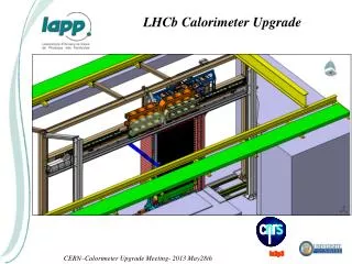
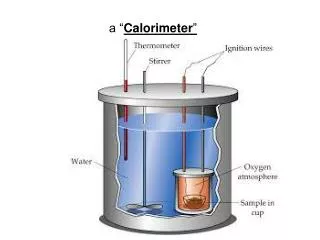
Real Environment • LHCb calorimeter: • Power Supply • Clock distribution • Trigger data flow • DAQ data flow Scintillator Pads Charged Particle Clock& Control Control Board VFE VFE VFE Ch-B Control Power Regulator Board Clock Data Data Preshower F.E. Board Selection Board SPECS Multiplicity Parallel session B2a - Production, testing and reliability Slide4
Real Environment • Data from VFE to PSFEB is composed by 4 LVDS serializers of 21b at 840Mbps each one. • Data from 7 PSFEB to a single CB is 7*840Mbps. • Data from CB to SB is about 1,2Gbps of payload with an optical link. • Control has I2C bidirectional control as well as a serial synchronous 40MHz channel for time sensitive controls. • Huge amount of data flows through the system Parallel session B2a - Production, testing and reliability Slide5
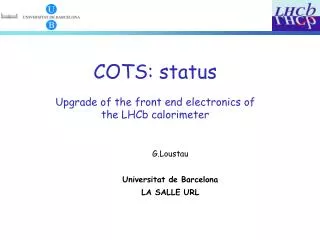
Former test boards • FPGA Baseline • Originally Parallax Board with Stratix EP1S25F672C6 • Nice solution for prototyping & tests (Discontinued by vendor) • Good form factor • Extended design done by our group • Same philosophy • USB instead of RS232, usable not only for programming. • Aprox. Double of pins • Backwards compatible • More powerful Stratix II EP2S60F484C5 Parallel session B2a - Production, testing and reliability Slide6
Former test boards • Control Board • Data from the backplane (PSFEB -> CB) • SPECS from the backplane • Optical Link Receiver • USB interface with a mezzanine by Bitwise Systems Parallel session B2a - Production, testing and reliability Slide7
Former test boards • Very Front End • Digital Part • PreShower Front End Board reception • Control of the VFE can be driven from the Control Board or from test board • Connection through real LDVS cable ensures maximum realism • USB interface with a mezzanine by Bitwise Systems • Can also work with the Photo Multiplier test environment to test the analogical part Parallel session B2a - Production, testing and reliability Slide8
Former test boards • Very Front End • Analogical Part • High voltage power supply for the PMTs • Dark box to test with controlled light • Motorized optical fiber emits pulsed light on the desired channel of the PMT • Also diffuse pulsed light is available • Motor control is done by a computer while triggering of light pulses is done by the VFE’s test board that also collects the resulting data Parallel session B2a - Production, testing and reliability Slide9
Former test boards • Link supervision • Clock distribution very important for our system, it defines integration time. Must be easily checkable. • Communication between the VFE/RB and the CB is done by an ad-hoc I2C with only two pairs. Focus of doubts, also tested. • Able to supervise signal shapes and communications. • Able to substitute a VFE and view what would it receive. • Able to check relative phases of the 8 clocks available on a CB. Parallel session B2a - Production, testing and reliability Slide10
Former test boards • Mixing real detector with “emulated” parts • Test for the data cabling with LVDS pattern • With real datapath • With test board instead of PSFEB • Test for analogical noise and offset • With real datapath • With test board instead of PSFEB • Test for the control cabling • With real datapath • With test board instead of CB • With scope • All of them very useful to isolate problems and try to solve them. Parallel session B2a - Production, testing and reliability Slide11
Final test board • USB • Ethernet • WiFi • LVDS Data • Control Cables • Optical • Power • PMTs env. • Spy Parallel session B2a - Production, testing and reliability Slide12
Final test board • Test capabilities VFE Test Control Board PMT Test Parallel session B2a - Production, testing and reliability Slide13
Final test board • Features • Mechanical resistance • One must not expect careful manipulation by an average user. • Old one had clear mechanical flaws. • Common in systems designed during prototyping tests. (Loose wires,...) Parallel session B2a - Production, testing and reliability Slide14
Final test board • Mechanical resistance • 21 screws, 10mm aluminium plate • Good fixation of optical link • Good fixation of LVDS cable Parallel session B2a - Production, testing and reliability Slide15
Final test board • Less laboratory dependant • Power • Clock • Scope • Special SW on PC • Now: • Clock generator • Power Regulator • No SW needed* Parallel session B2a - Production, testing and reliability Slide16
Final test board • Better interface: • USB • Ethernet/WiFi (compatible with various models with integrated web server) • Portable: • O.S. Independent (No drivers) • No applications • Always Updated software • Usable: • Remotely operated (expert at home, ALARA reasons, etc) Parallel session B2a - Production, testing and reliability Slide17
Conclusions • Ready for future tests and reparations • System suitable for average user • Usable • Stable • Intended for average user • Better interface • Ethernet is a great advantage • More test possibilities • New data paths not available before • Less lab dependant • Solved problems learned by using testing boards Parallel session B2a - Production, testing and reliability Slide18