Download
1 / 28
590 likes | 1.42k Views
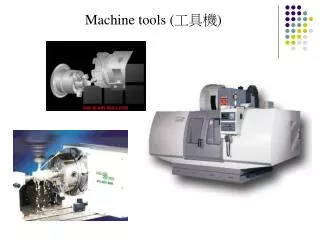
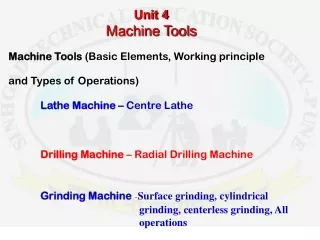
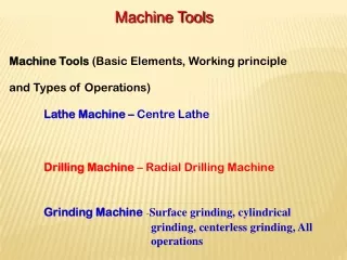
MACHINE TOOLS. A Machine tool. A machine tool may be defined as a power driven machine which accomplishes the cutting or machining operations in it. Examples: Lathe, Drilling machine, Milling machine, Grinding machine. Shaping machine .

E N D
MACHINE TOOLS Dept. of Mech & Mfg. Engg.
A Machine tool A machine tool may be defined as a power driven machine which accomplishes the cutting or machining operations in it. Examples:Lathe, Drilling machine, Milling machine, Grinding machine. Shaping machine Dept. of Mech & Mfg. Engg.
Functions of Machine Tools • To hold and support job/work to be machined • To hold and support the cutting tool in position • To move the cutting tool, work or both in a desired direction • To regulate cutting speed and provide feeding movement.
Working principle of lathe Chuck Direction of rotation of work piece Work piece Cutting tool Direction of cutting tool Dept. of Mech & Mfg. Engg.
Chuck Direction of rotation of work piece Cutting tool Direction of cutting tool Working principle of a lathe • Cutting tool can remove material in the form of chips from rotating work pieces to produce circular objects • Work piece is held rigidly by one of the work holding devices known as chuck • Uses V – shaped cutting tool Dept. of Mech & Mfg. Engg.
Lathe Basics Spindle Nose Tailstock Spindle Clamp Tool Post Compound Rest HEADSTOCK TAILSTOCK Saddle Feed Change Lever Feed Reverse Lever Lead Screw BED WAYS APRON Bed Half Nut Lever Friction-clutch Control Gear Box Carriage Hand Wheel Motor Drive Cross Slide Dept. of Mech & Mfg. Engg.
Explain with neat diagram the principal parts of an engine lathe. Dept. of Mech & Mfg. Engg.
LATHE Dept. of Mech & Mfg. Engg.
MAJOR PARTS 1] Bed 2] Head stock 3] Tail stock 4] Main drive 5] Carriage assembly consisting of a) Saddle b) Cross-slide c) Compound rest d) Tool post e) Apron 6] Lead screw 7] Feed rod Dept. of Mech & Mfg. Engg.
BED • Foundation part of the machine • Supports all other parts • The top of the bed is formed by two Precession guide ways • i) Outer guide way--- Carriage assembly mounted and align it with centre line of lathe • ii) Inner guide way--- Head stock and Tailstock are mounted Dept. of Mech & Mfg. Engg.
Headstock: • Housing comprising of • feed gear box • stepped cone pulley • Rigidly mounted on the inner guide ways of lathe bed at its left end. Dept. of Mech & Mfg. Engg.
MAIN DRIVE Cone pulley • Cone pulley which drives the main spindle is driven by the motor. • Various spindle speeds can be obtained by shifting the belt on differentsteps of the cone pulley. Dept. of Mech & Mfg. Engg.
Tailstock: • Movable part of the lathe that carries the dead centre in it. • Used to clamp tools like: Twist drills Reamers For making holes. • Mounted loosely on the inner guide ways of a lathe bed • Moved and locked in any position. Dept. of Mech & Mfg. Engg.
Carriage assembly: • To support the tool • Moves over the outer guide ways longitudinally between headstock and tailstock. It is composed of 5 main parts: • Saddle • Cross slide • Compound Rest • Apron • Tool post Dept. of Mech & Mfg. Engg.
Lathe Carriage and Apron Tool Post Compound Rest Carriage Lock Screw Cross Feed Knob Cross Slide Apron Hand Wheel Half Nut Lever Compound Rest Knob Dept. of Mech & Mfg. Engg.
Saddle • H shaped casting that slides over set of guide ways • Serves as the base for the cross slide. Cross slide • Mounted on the saddle • Enables the movement of the cutting tool laterally across the lathe bed by means of cross feed hand wheel. Dept. of Mech & Mfg. Engg.
Cross Feed Knob Used to move cutting tool across the end of the stock - Facing (Cross Feed) Dept. of Mech & Mfg. Engg.
Compound Rest • Mounted on the top of the cross slide • Supports the tool post. • Swiveled to any angle in the horizontal plane • To facilitate following operations: • Taper turning • Threading operations Dept. of Mech & Mfg. Engg.
Apron Hand Wheel Used to move tool along the work - for Turning (Longitudinal Feed) Apron Hand Wheel Dept. of Mech & Mfg. Engg.
Apron • Mounted on the front of the saddle • Consists of, - Carriage - Cross slide mechanisms Tool Post Compound Rest Tool post • Clamps the tool holder in the proper position for machining operations. Dept. of Mech & Mfg. Engg.
Chuck Three Jaw Chuck - For holding cylindrical stock centered. Dept. of Mech & Mfg. Engg.
Lead Screw: • A screw rod which moves longitudinally in front of the lathe bed. • Rotation of the lead screw moves the carriage to and fro longitudinally during thread cutting operation. Dept. of Mech & Mfg. Engg.
Feed rod: • A stationary rod mounted in front of the lathe bed • Facilitates longitudinal movement of carriage during turning and facing operations. Dept. of Mech & Mfg. Engg.
Center Drilling Dept. of Mech & Mfg. Engg.
Turning Between Centers Dept. of Mech & Mfg. Engg.