Download
1 / 8
80 likes | 175 Views
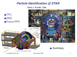
MICE Upstream Particle Identification. Tom Roberts Illinois Institute of Technology March 30, 2004. JAN04 MICE Beamline. (MAR04 differs only by changes in magnet positions, primarily ~30% increase between TOF0 and TOF1). Upstream Cherenkov (proposed). ISIS Beam. TOF0. TOF1. Tracker1.

E N D
MICE Upstream Particle Identification Tom Roberts Illinois Institute of Technology March 30, 2004
JAN04 MICE Beamline (MAR04 differs only by changes in magnet positions, primarily ~30% increase between TOF0 and TOF1) Upstream Cherenkov (proposed) ISIS Beam TOF0 TOF1 Tracker1 (3-D view approximately a plan view)
Why These positions? • TOF0 • Must be after B2 • Behind Q4 to reduce singles • As far forward as possible to maximize TOF1-TOF0 distance • TOF1 • Must be after TOF0 • As far back as possible to maximize TOF1-TOF0 distance • As far back as possible to let more pi+ decay • Ahead of Q9 for magnetic shielding from Tracker1 solenoid • As far back as possible to minimize singles and pileup • Cherenkov1 • Must be after TOF0 • As far back as possible to let more pi+ decay • Needs smaller magnetic field than TOF0/TOF1 • Needs more space than TOF0/TOF1 • As far back as possible to minimize singles and pileup
Can we really intersperse the TOFs and Quads? • Simulations show that the maximum excursion in the quads corresponds to less Δt than the TOF resolution • Back of the Envelope: It seems quite reasonable to intersperse the TOFs and Quads. Besides, we don’t really have space in the hall to do otherwise.
JAN04 Beamline TOF1-TOF0 Performance (Red dots are bigger than blue dots) • Includes: • TOF resolution of 50 ps • Momentum measured in Tracker1, with resolution 2-25 MeV/c depending on P┴ • JAN04 beamline (MAR04 has 30% longer distance) • Events generated to fill the Q4 aperture, with pi/mu=1 (really ~0.02 at TOF1, ~0.002 for good-μ+)
π+Beam-Related Singles Rates Rate is kHz during the 1 ms per second of good Target & RF Other backgrounds are not included.
A Note About These Singles Rates • In Abingdon we decided we need 600 good-mu+/second • JAN04 does not achieve that rate with the target assumptions used • To achieve 600 good-mu+/sec we will need to insert the target deeper into the ISIS beam (assuming losses permit that) • That will increase all singles rates proportionally • That implies 12-15 MHz at TOF0 is not unlikely • Note that the JAN04A tune had a factor of 6x more good-mu+/sec than JAN04, with only a few percent increase in TOF0 singles – it did this by keeping more muons in the cooling channel, not by getting more into TOF0 • Note also that these rates are for JAN04 – we need to simulate MAR04 and obtain corresponding rates