Download
1 / 53
530 likes | 664 Views
WBS 1.1 EMU Chambers. Cathode Strip Chambers Andrey Korytov L3 Manager. Outline. System Overview CSC Group Organization R&D: - cost efficient design - performance results CSC Production Plan, Production Sites Schedule, Milestones US Deliverables Base Cost Analysis Contingency

E N D
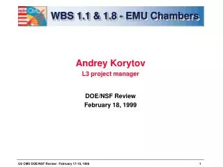
WBS 1.1 EMU Chambers • Cathode Strip Chambers • Andrey Korytov • L3 Manager
Outline • System Overview • CSC Group Organization • R&D: - cost efficient design - performance results • CSC Production Plan, Production Sites • Schedule, Milestones • US Deliverables • Base Cost Analysis • Contingency • Summary
CMS Endcap Muon System Large CSCs (3.4x1.5 m2): 72 ME2/2 chambers 72 ME3/2 chambers Small CSCs (1.8x1.1 m2): 72 ME1/2 chambers 72 ME1/3 chambers 20o CSCs (1.9x1.5 m2): 36 ME2/1 chambers 36 ME3/1 chambers
Performance requirements • Operation:very reliable (limited access) • Offline Resolution:75 mm per chamber (ME1/2) • 150 mm per chamber (others) • Trigger: ~1 mm resolution per chamber • fast (>92% within 25 ns window) • Rates:~300-1000 Hz/cm2 (random hits) • ~100 Hz/cm2 (charged particles) • no aging up to 0.1 C/cm (10 years of LHC) • B-field: non-uniform and up to 1 T
Cathode Strip Chambers • Same chamber: presision measurements + trigger • offline spatial resolution ~50 mm • trigger spatial resolution ~1 mm in presence • of electromagnetic debris (6-layer CSC) • fast timing: <25 ns for 6-layer CSC • Can work in difficult environment: • high rate capabilities (~1 kHz/cm2) • large (4 Tesla) and non-uniform B-field • Also: • two coordinates from single plane • strips can be shaped to measure f-coordinate; alignment marks are easy • no stringent control of gas mix, temperature, and pressure
CMS EMU CSCs • trapezoidal chambers • length up to 3.4 m • width up to 1.5 m • 6 planes per chamber • 9.5 mm gas gap (per plane) • 6.7 to 16.0 mm strip width • strips run radially to measure f-coordinate • 50 µm wires spaced by 3.2 mm • 5 to 16 wires ganged in groups • wires measure r-coordinate • gas Ar+CO2+CF4=30+50+20 • HV=4.1 kV (Qcathode~110 fC, Qanode~140 fC)
CSC Group institution involvement UC Davis - Simulation Production (UCLA Site) UCLA - R&D, Design Production (UCLA and Fermilab Sites) UC Riverside - R&D Production (UCLA Site) Carnegie Mellon - R&D, Design Fermilab - R&D, Design Production (Fermilab Site) Florida - R&D, Design Production (UF and Fermilab Sites) Livermore - R&D Ohio State - R&D, Design Purdue - R&D, Design Production (Fermilab Site) Wisconsin - R&D, Design Production (Fermilab Site) PNPI - St.Pitersburg - R&D, Design Production (PNPI Site) IHEP - Beijing - Design Production (IHEP Site)
CSC R&D Goals • CSC Cost Minimization: • Simple and Robust Design: • geometry to allow for relaxed tolerances • minimal number of parts and simple assembly • Identify Cost Driving Materials, minimize their cost: • find readily available commercial products • Identify Cost Driving Labor, minimize cost : • automate labor intensive operations • minimize in-house labor, i.e. place orders in industry • testing in the production to minimize repairs • Maintain Adequate Performance: • Reliable operation at Qcathode>100 fC • 75-150 mm off-line spatial resolution • ~1 mm trigger spatial resolution • >92% probability of correct bunch crossing assignment
milled strips long wires 2 different wires (30 mm Luma, 50 mmSylvania) 70 144 cm ´ guard strips/wires different discriminators w=10 mm and none s=2.5 mm , 2r=30/50 m m 2 70 144 cm ´ w=10 mm and none s=2.5 mm , 2r=30/50 m m R&D: CSC Prototypes P0 (1995) - muon beam performance tests T0 (1994) - design tests 6 planes 60x60 cm2 w=16 mm s=2.5 mm 2r=30 mm 2 planes "top" of large CSC (ME2/2) s(x/w), timing, efficiencies, tails P0’ (1996) - muon beam performance tests T1A (1995) - design tests new winding technique s=3.2 mm (no wire support, timing!) HV segmentation, buttons RTV gas sealing strips milled with 45-degree cutter grinding was used to make gap bars 6 planes 60x60 cm2 w=6 mm s=3.4 mm 2r=50 mm T1B (1995) - design tests "bottom" of precision CSC (ME1/2) s(x/w), timing, efficiencies, tails, 1/2-strip finding trigger hardware LCT in presence of e/m debris 2 planes (both T1A and T1B) P1A (1996) - large scale design tests 2 planes 3.3 m long 1.2-0.8 m wide w=16-10 mm s=3.2 mm 2r=50 mm P1 (1996) - large scale complete chamber 6 planes 3.3 m long 1.2-0.8 m wide w=16-10 mm s=3.2 mm 2r=50 mm P2 (1997) - full scale 1:1 large chamber 6 planes 3.3 m long 1.5-0.8 m wide w=16-8 mm s=3.2 mm 2r=50 mm detailed performance studies: cosmic ray tests first complete set of final electronics prototypes 1998 muon beam tests 1998 high rate tests (muon beam + gammas)
CSC Design : Single Plane Parameters • Large Gas Gap -- 10 mm (cf. 5-10 mm) • relaxes panel flatness tolerances • allows for wider strips (save on electronics channels) • Thick Wires -- 50 mm (cf. 20-30 mm) • very robust mechanically • Large Wire Spacing -- 3.2 mm (cf. 2-2.5 mm) • relaxes wire placement tolerances • no intermediate wire supports • fewer wires
CSC Design: overall chamber Design is simple (few parts), robust, and suitable for mass production
CSC Design: Cost Driving Materials • Cost Driving Materialshave been identified: • Panels • Wires • Gap Bars • Wire Fixation Bars • Significant cost reduction of these materials has been achieved as a result of an extensive R&D (still they constitute 74% of the overall material cost) • All material costs based on vendor quotes • Materials tested on large prototypes
CSC Design: Panels - material cost driver • Panels from 3 bidders (out of 11 - see on the right) were ordered • flatness, mechanical properties studied (CMS Note 1995-094) • Plascore was chosen: • panels with FR4 skins (ready product) • very stable polycarbonate core • flat within our spec.’s • inexpensive • willing to work on technology improvements • EuroComposite and Teklam are fallback options • A few batches of panels from Plascore have been ordered since 1995 • All large prototypes (and most of small ones) were made out of these panels • and showed very reliable performance Panel Manufacturers AAR Cadillac ACT Advanced Composites EuroComposite Hexcel M.C.Gill Norfield Oregon Composites Plascore Teklam Todco
CSC Design: Wires - material cost driver • Large MWPC Systems used Luma wire: $587/km for 50 mm wire • Sylvania quote for similar wire: $144/km (also used in MWPCs) • Sylvania and Luma wires were purchased and thoroughly tested, • thus, we could directly compare Sylvania wire against Luma’s • visual analysis under microscope: good • elasticity limit and breakage point: good • breakage under sparking: good • chamber performance: good • All large scale prototypes have Sylvania wire • and have shown reliable operation
CSC Design: Cost Driving Labor • Strategy for minimizing labor cost: • robust and simple chamber design, suitable for mass production • labor intensive operations are identified and automated/optimized: • strip milling vs. etching • wire winding • wire soldering • gluing • parts are purchased from commercial vendors to minimize in-house labor • testing along chamber assembly to minimize repairs
CSC Design: Strips - labor cost driver • Lowest etching quote (two bidders: CCT, Buckbee-Mears): • $9,549 per chamber (9 panel sides) • plus $104K initial investment is required • Milling (all based on large scale prototypes): • ~1 hour (per plane with 80 strips):fast • ~ 25 mm precision:good • 45o cutter mills with almost etching quality:good • smooth vs. milled cathode CSC performance:identical • With all handling, cleaning and testing, milling will cost • $1,900 per chamber, i.e. 5 times cheaper (~$2M of savings) • All prototypes (except for the small P0) have had milled strips • and showed very reliable operation
CSC Design: Wire Winding - labor cost driver • Transfer frames: too labor intensive • New winding machine to wind directly on panels: • two planes (1000 wires each @4 turns per min) - less than one shift • minimum handling • no asymmetric stresses on a panel • Chamber prototype results: • uniform tension ±5% (we need ±10%) • wire spacing ±100 µm (we need ±200 µm) • All prototypes showed very reliable operation
CSC Design: Wire Soldering - labor cost driver • Hand-soldering (P1A large scale prototype: 1000 wires per plane): • 2 FTEs x 6 days per 6-plane chamber • Robotic soldering machine was built at Fermilab • using commercially available automated soldering head (Panasonic): • - 3.5 sec per soldering joint (tested on P2 full scale CSC), • - high quality and uniformity of soldering joints • Projected Time with all handling, wire cutting, etc: • 1 FTE x 4 days per 6-plane chamber, • i.e. 3 times faster than hand soldering • Estimated Savings at Fermilab Production Site • $270K (labor) - $90K (machine investment) = $180K • P2 protototye (full scale large CSC) works reliably since January 1998
Performance R&D: Operation Reliability • P1A, P1, P2 large scale prototypes: • operation point at 4.1 kV and at 4.5 kV prototypes are still operational • P1 has been under HV for more than a year • P1A shipped twice, P1 shipped once: no problems (a >10g) • Aging Studies: • 10 years of LHC at full luminocity: ==> accumulated charge on wires is ~0.1 C/cm • Use of CF4 gas is know to prevent aging: ==> no aging effects up to 10 C/cm • CSCs made according to our design and out of the design materials • 20% CF4 - chamber irradiated in excess of 13 C/cm • 10% CF4 - chamber irradiated in excess of 13 C/cm (high gas flow) plus • additional 0.7 C/cm accumulated at gas flow rate 0.1 V/day • and 1.5 C/cm at gas flow of 1 V/day (nominal) • No gas gain variations were observed. Dark current remained small.
400 300 Spatial Resolution, s (mm) 200 100 six plane chamber resolution (MC) 0 0 0.2 0.4 0.6 0.8 1 Hit coordinate across strip (x/w) Performance R&D: Off-line Spatial Resolution solid points: single plane resolution in cosmic rays for top ( ), middle ( ), bottom ( ) parts of the trapezoidal CSC (P1 prototype) solid curves: single plane resolution Monte Carlo dashed curves: 6-plane resolution as extrapolated from single plane data P1 - large scale prototype Chamber planes are half-strip staggered and expected six-plane resolution is ~80 mm, i.e. well within 150 mm spec.
Performance R&D: Trigger Spatial Resolution s=0.7 mm • BEAM TEST RESULTS: • comparators find hits to within a 1/2-strip with 92% efficiency • six-plane patterns (LCTs) are found with 99% efficiency • and 0.11(strip width) ~ 0.7 mm resolution • in presence of em debris accompanying muon behind the iron
Nominal Operating Point 1.0 Probability (92% requirement) 0.8 0.6 2nd out of 6 1st out of 6 0.4 0.2 0.0 3.6 3.8 4.0 4.2 4.4 4.6 HV, kV Performance R&D: Trigger Bunch Tagging • 6-plane patterns are found with • 99.5% efficiency • (smaller prototype beam tests) • Time stamp: 97% probability to be • within 25 ns window • for the 2nd earliest signal • out of 6 hits in an LCT pattern • (well within the required 92%) P1 - large scale prototype
CSC Design Summary • Chamber Design is optimized • Cost Drivers (materials and labor) are identified • and their cost is well understood and minimized • Mass Production Tooling is prototyped • Full Scale Chamber Prototypes meet our requirements
CSC Production Plan • Production is divided between five sites: • Fermilab site • UC site • UF site • PNPI - St.Petersburg site • IHEP - Beijing site • optimal use of Fermilab infrastructure and university contributions • use of the base program resources at Fermilab and universities: • - chamber construction and tooling experts • - physicists with expertise in chambers and electronics • use contributions from CMS collaborators (PNPI-St.Petersburg, • IHEP-Beijing): assembly of smaller chambers (~$4M in US costs) • one common chamber dsign • all parts and critical tooling made in US • same assembly and test procedures on all sites
CSC Production Sites • Fermilab site (Fermilab/university consortium): • - procurement of chamber parts for all chambers • - strip milling for all chambers • - assembly and HV-training of large chambers (148 ME23/2) • - sample testing • UC and UF sites: • - outfitting large chambers with electronics and services • - system tests of large chambers • - installation, commissioning, maintenance of large chambers • PNPI and IHEP sites: • - assembly and tests of smaller chambers • - installation, commissioning, maintenance of smaller chambers • all parts and critical tooling are provided by US • labor is covered by PNPI and IHEP--it is their contribution to CMS
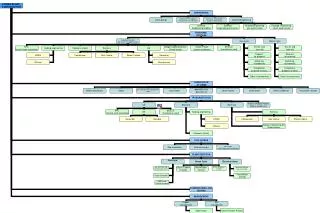
CSC Production PNPI Site parts and critical tooling (smaller chambers) smaller CSCs+Electronics, tested installation/commissioning large CSCs UC Site large CSCs+Electronics, tested installation/commissioning Fermilab Site: - panel production - large CSC assembly CERN large CSCs+Electronics, tested installation/commissioning large CSCs UF Site Procurement parts and critical tooling (smaller chambers) etc. smaller CSCs+Electronics, tested installation/commissioning frames guard strips gap bars IHEP Site wire fix bars wire panels
Fermilab Site: Panel Milling Location: Lab 8 Operations: Inspection: incoming panels (thickness, flatness, etc.) Axxiom Machine: drill holes, cut trapezoids Gerber Machine: mill strips, cathode and anode artwork Certification: milled panels cleaned, milling quality certified Packaging: panels wrapped for storage & shipping
Fermilab Site: CSC Assembly Location: MP-9 Operations: Gluing Station: - glue wire fixation bars - glue long and short guard strips - glue gap frame bars Winding+Soldering Station: - wind wires on panels, glue wires - solder wires, cut wires Pre-Assembly/Testing Station: - solder Rs, Cs, connectors, protection boards - test HV in air; wire tension/spacing (sample) Assembly Station: - stack panels and Al frame bars, test HV - tighten bolts, RTV seal - wire HV connectors HV-training Station: - HV-training of chambers Repair Station
Final Assembly & System Tests Sites Location: UCLA and UF Operations: Long Term HV-Conditioning Final Assembly: - services and gadgets - electronics cards and enclosures (10 units per chamber) - cabling, marking cables (~100 different cables per chamber) Tests without HV: - cable connections (no mix-ups) - no dead channels, oscillations, pickup noise (ground/shield) - electronics-on-chamber (strip calibration, thresholds, delays) Tests with HV: - HV is properly filtered - determine operation point for each plane (gas gain, efficiency) - minimum plateau with respect to Idark and Nnoise (wires/strips) - tune anode LCT timing w.r.t. to cosmic muons - time matching between anode and cathode LCTs Detailed tests: - time permitting (not necessarily on each chamber) Chamber repairs Database
CSC Production Schedule Lab 8 MP 9 UC Site UF Site PNPI IHEP 1999 22 6 /.5 yr 2000 98 17 8 8 2001 98 50 25 25 20 38 2002 98 50 25 25 26 50 2003 56/.5 yr 25/.5 yr 16/.5 yr 16/.5 yr 30 60 Panel Count by CSC type at Lab 8 ME23/2 ME23/1 ME1/23 TOTAL 1999 22 22 2000 42 20 36 98 2001 42 20 36 98 2002 42 20 36 98 2003 (1/2 yr) 16 40 56
Major CSC Milestones • 01/01/98 P2 (ME23/2) 1:1 scale prototype • 12/20/98 ME23/2 - final design • 11/16/98 ME2/2 Preproduction Prototype • 12/08/98 ME2/1 Prototype • 01/15/99 Panel Production Design Review • 03/16/99 Panel Production Site is ready, Start of panel production • 12/21/99 22 ME23/2 CSC worth of panels made, Full Speed Production begins in Jan 2000 • 03/15/99 Chamber Assembly Design Review • 07/01/99 Chamber Assembly Site is ready, Start of ME23/2 chamber assembly • 12/21/99 6 ME23/2 CSCs assembled, Full Speed Production begins in Jan 2001 • 12/21/99 ME3/1 and ME1/2 Preproduction Prototypes, small chamber design review • 12/20/00 PNPI and IHEP Sites ready, Start of Small Chamber Production in Jan 2001 • 12/21/99 FAST sites are ready, Start of detailed CSC tests with prototype electronics • Full Speed Final Assembly and Testing begins in July 2000 • 07/01/03 First Endcap CSCs are installed • 03/01/04 Second Endcap CSCs are installed
WBS 1.1 Deliverables • Design Deliverables • Cathode Strip Chambers:ME1/2, ME1/3, ME2/1, ME3/1, ME23/2 • CSC production tooling • CSC testing equipment and procedures • High Voltage System • Production Deliverables • 144+4=148 large ME23/2 chambers: production of parts, assembly, outfitting with electronics, testing, commisssioning at CERN (Fermilab, UC, UF sites) • All parts for smaller CSCs (assembly kits): • 36+2=38 ME2/1, 36+2=38 ME3/1 (to be assembled/outfitted/tested at PNPI) • 72+2=74 ME1/2, 72+2=74 ME1/3 (to be assembled/outfitted/tested at IHEP) • Critical tooling and testing equipment for PNPI and IHEP sites • High Voltage for all ME1/2, ME1/3, ME2/1,ME3/1, ME23/2
CSC Cost Estimate: WBS L3 M$12.835 (base, in FY97 $) + 42% (Contingency) = M$18.227
CSC Base Cost Estimate: Details • CSC Base Cost = M$12.835
CSC Cost: material cost database • I. Parameters, Parts for all CSCs
CSC Cost: material cost database • II. Quotes are linked to the part list
CSC Base Cost Estimate: Labor • construction of the full scale prototypes (P1, P2) is the basis for the estimate • major and most of minor tooling protypes have been used in the full scale chamber prototypes assembly • all operations have been timed • operations at individual production stations are outlined in space and time • 80% efficiency is assumed (Lab 8, Lab 6 experience), i.e. manpower assumed is sufficent to make 1 CSC every 4 days, whileaverage yeald is assumed to be 1 CSC every 5 days • tooling capability is 1 CSC every 3 days in one shift • soft production ramp-up is built in • standard Fermilab and University labor rates are assumed
CSC Cost: Labor at peak of production Fermilab: 1 PhD supervisor (senior) Lab 8: 1 PhD supervisor 0.5 tech. supervisor (P.Deering) 2 CNC operators (1 Axxiom, 1 Gerber) 1 tech (cleaning/inspection/wrapping) 0.4 tech’s (2 tech’s one day a week for handling/shipping/etc.) MP 9: 1 PhD supervisor 1 tech. supervisor (K.Kephart) 7 tech’s (primary assembly stations) 1 specialist (testing/HV-training expert) 2 PhD’s (repairs/tests/etc.) FAST Sites: 1 PhD supervisor (senior) 1 PhD lab physicist (full time in the lab) 1 tech (outfitting with services, electronics, handling, etc.) 1 expert (electronics/chamber problem debugging) 2 FTE students (1 FTE assembly, 0.5 cathode work, 0.5 anode work)
Contingency: MFxJF Materials: maturity factor (MF): 1.0 - purchased 1.1 - catalog item, P.O. 1.2 - vendor quote 1.3 - complete design (TDR) 1.4 - indirect estimate, request for info w/sketches 1.5 - estimate based on conceptual design judgment factor (JF): 1.0 - standard, simple, we buy now at this price 1.1 - extracted from very similar quote 1.2 - chain of vendors - not 100% prototyped 1.3 - single vendor 1.4 - lack of knowledge (not prototyped) contingency on not purchased materials: cannot be less than 20%
Contingency: MFxJF Labor and Engineering: maturity factor (MF): 1.25 - vendor quote and/or complete design judgment factors (JF): 1.0 - coordination, management 1.1 - labor directly verified on prototypes 1.2 - not 100% prototyped 1.4 - lack of knowledge (not prototyped)