Download
1 / 59
590 likes | 596 Views
This research focuses on the study of electron clouds and low emittance tuning techniques in order to develop strategies for mitigating electron cloud effects and achieving low emittance in the damping rings of the International Linear Collider (ILC). The research aims to measure the dependence of electron cloud growth on various parameters and to study instabilities and other current-dependent effects. Strategies for tuning vertical emittance and achieving low emittance optics are also being developed.

E N D
CesrTA Low Emittance and Electron Cloud R&D David Rubin Cornell Laboratory for Accelerator-Based Sciences and Education
ILC Reference Design • 11km SC linacs operating at 31.5 MV/m for 500 GeV • Centralized injector • Circular damping rings for electrons and positrons • Undulator-based positron source • Single IR with 14 mrad crossing angle BNL
ILC Damping Rings • Beam Parameters • 2625 bunches/ RF pulse • Pulse rate - 5.0Hz • Pulse length ~ 0.8 ms (240 km) • Bunch spacing in linac ~ 300ns • Particles/bunch - 2X10¹⁰ • Beam emittance ~ x= 0.8nm, y = 2pm (at 5GeV) • Damping rings (1 for electrons, 1 for positrons) • Ebeam = 5 GeV • ~ 6 km circumference (20 s revolution period) 3ns bunch spacing It is anticipated that the electron cloud will limits positron current/emittance Viability of the design depends on development of suitable - electron cloud mitigation and - low emittance tuning techniques BNL
Electron Cloud • What is the electron cloud? • Synchrotron radiation from the circulating positrons, strikes the walls of the • vacuum chamber and photoelectrons are emitted • An electron cloud evolves and is trapped in the path of the beam by the beam • potential and the magnetic fields of dipoles, quadrupoles, and especially wigglers • Focusing of e-cloud on circulating bunches shifts tune and dilutes beam emittance • E-Cloud couples transverse motion of one e+ bunch to the next, • eventually destabilizing the bunch train schematic of e- cloud build up in the arc beam pipe, due to photoemissionand secondary emission [Courtesy F. Ruggiero] BNL
CesrTA Objective Provide a laboratory for the study of electron cloud phenomena in a parameter regime that approximates ILC damping rings to measure • Dependence of e-cloud growth on • Beam current, bunch spacing, beam size • Magnetic field • Vacuum chamber geometry and chemistry • Beam energy • Mitigation techniques (coatings, clearing electrodes, grooves, etc.) • Enable measurement of instabilities and other current dependent effects in the ultra low emittance regime for both electrons and positrons Such as dependencies of • Vertical emittance and instability threshold on density of electron cloud • Cloud build up on bunch size • Emittance dilution on bunch charge (intrabeam scattering) BNL
CesrTA Objective Develop strategies for systematically tuning vertical emittance • Rapid survey • Efficient beam based alignment and correction algorithms • Demonstrate ability to reproducibly achieve our target of < 20 pm (geometric) • In CesrTA this corresponds to a vertical beam size of about ~ 20microns BNL
Low Emittance Tuning Outline • CesrTA optics • Horizontal emittance in a wiggler dominated ring • Sensitivity of horizontal emittance to optical and alignment errors • Contribution to vertical emittance from dispersion and coupling • Dependence of vertical emittance on misalignments of guide field elements • Beam based alignment • Alignment and survey • Dependence on BPM resolution • Beam position monitor upgrade • Beam size monitors • Intensity dependent effects • First experiments with low emittance optics BNL
Low Emittance Optics wigglers Wiggler dominated: 90% of synchrotron radiated power in wigglers BNL
Low Emittance Optics • CesrTA Configuration: • 12 damping wigglers located in zero dispersion regions for ultra low emittance operation (move 6 wigglers from machine arcs to L0) CESR-c Damping Wiggler BNL
L0 wiggler experimental region design work well underway Installation during July down Heavily instrumented throughout with vacuum diagnostics Note: Part of CLEO will remain in place At present unable to remove full detector Time savings L0 Wiggler Region MAIN COMPONENT POSITIONS TILC08 - Sendai, Japan
Low Emittance Optics Emittance scaling with energy and tune ~ E2/Qh3 9 (nm) at Qh=14.52, E=2GeV Emittance scaling with wigglers HEP configuration - taylor H in wigglers to increase emittance Damping ring configuration - minimize H in wigglers 12, 2.1T wigglers in CESR at 2GeV/beam increases I2 X 10 In the limit where I2(arc)I2(wiggler), and I5(arc) 0, and =’ =0 at start and end of wigglers, The contribution of a single wiggler period is: BNL
Wiggler Emittance Dependence of emittance on number of wigglers Zero current emittance In CesrTA - 90% of the synchrotron radiation generated by wigglers BNL
Minimum horizontal emittance Can we achieve the theoretical horizontal emittance? How does it depend on optical errors/ alignment errors? Correct focusing errors - using well developed beam based method • Measure betatron phase and coupling • Fit to the data with each quad k a degree of freedom • Quad power supplies are all independent. Each one can be adjusted so that measured phase matches design • On iteration, residual rms phase error corresponds to 0.04% rms quad error. residual dispersion in wigglers is much less than internally generated dispersion • We find that contribution to horizontal emittance due to optical errors is neglible. • Furthermore we determine by direct calculation that the effect of of misalignment errors on horizontal dispersion (and emittance) is negligble We expect to achieve the design horizontal emittance (~2.3nm) BNL
Sources of vertical emittance • Contribution to vertical emittance from dispersion • Dispersion is generated from misaligned magnets • Displaced quadrupoles (introduce vertical kicks) • Vertical offsets in sextupoles (couples horizontal • dispersion to vertical) • Tilted quadrupoles (couples x to y) • Tilted bends (generating vertical kicks) • Contribution to vertical emittance from coupling • Horizontal emittance can be coupled directly to vertical • through tilted quadrupoles BNL
Beam Based Alignment • Model ring • Magnet misalignments • Magnet field errors • Beam position monitor offsets and tilts • BPM resolution [absolute & differential] • “Measure” • Orbit • Dispersion • Betatron phase • Transverse coupling • Fit - (using dipole and skew quad correctors) • Fit “measured” betatron phase to ideal model using ring quadrupoles • Fit “measured” orbit to ideal model using dipole correctors • Fit “measured” dispersion to ideal model using dipole correctors • Fit “measured” transverse coupling to ideal model using skew correctors (Thanks to Rich Helms) BNL
Misalignments For CesrTA optics: Use gaussian distribution of alignment errors to create “N” machine models and compute emittance of each BNL
Dependence of vertical emittance on misalignments nominal For nominal misalignment of all elements, v < 270pm for 95% of seeds BNL
Misalignment tolerance Contribution to vertical emittance at nominal misalignment for various elements Target emittance is < 20 pm BNL
Beam Based Alignment • Beam base alignment algorithms and tuning strategies (simulation results) • Beam based alignment of BPMs(depends on independent quad power supplies) • Y < 50m • Measure and correct • -phase design horizontal emittance • Orbit reduce displacement in quadrupoles (source of vertical dispersion) • Vertical dispersion minimize vertical dispersion • Transverse coupling minimize coupling of horizontal to vertical emittance • Minimize -phase error with quadrupoles • Minimize orbit error with vertical steering correctors • Minimize vertical dispersion with vertical steering correctors • Minimize coupling with skew quads BNL
One parameter correction • CESR correctors and beam position monitors • BPM adjacent to every quadrupole (100 of each) • Vertical steering adjacent to all of the vertically focusing quadrupole • 14 skew quads - mostly near interaction region • The single parameter is the ratio of the weights • Three steps (weight ratio optimized for minimum emittance at each step) • Measure and correct vertical orbit with vertical steerings minimize i (wc1[kicki]2 + wo [yi]2 ) • Measure and correct vertical dispersion with vertical steering minimize i (wc2[kicki]2 + w[i]2) • Measure and correct coupling with skew quads minimize i (wsq[ki]2 + wc[Ci]2) BNL
Tuning vertical emittance • Evaluate 6 cases 2 sets of misalignments: 1. Nominal and 2. Twice nominal(Worse) X 3 sets of BPM resolutions: 1. No resolution error, 2. Nominal, and 3.Worse (5-10 X nominal) v=109m May 07 survey (one turn) ~ 27m (Nturn average) ~ 27m/N *The actual error in the dispersion measurement is equal to the differential resolution divided by the assumed energy adjustment of 0.001 BNL
Low emittance tuning Vertical emittance (pm) after one parameter correction: With nominal magnet alignment, we achieve emittance of 5-10pm for 95% of seeds with nominal and worse BPM resolution With 2 X nominal magnet alignment yields emittance near our 20pm target BNL
Two parameter correction Consider a two parameter algorithm Measure orbit and dispersion. Minimize i wc2[kicki]2 + wo2 [yi]2 + w1[i]2 Measure dispersion and coupling. Minimize i wsq[ki]2 + w2[i]2 + wc[Ci]2 The two parameters are the ratio of the weights. The ratios are re-optimized in each step Vertical emittance (pm) after one and two parameter correction: 2 X nominal survey alignment, 10m relative and 100m absolute BPM resolution - 2 parameter algorithm yields tuned emittance very < 20pm for 95% of seeds BNL
Alignment and Survey Instrumentation - new equipment Digital level and laser tracker Network of survey monuments Complete survey in a couple of weeks Magnet mounting fixtures that permit precision adjustment - beam based alignment BNL
BPM resolution Relative BPM resolution critical to measurement of vertical dispersion Dispersion depends on differential orbit measurement v = [y(/2) - y(-/2)]/ ~1/1000 In CesrTA optics dependence of emittance on vertical dispersion is v ~ 1.5 X 10⁻⁸ 2 Emittance scales with square of relative BPM error (and the energy offset used to measure dispersion) (single pass) ~ 27m (N turn average) ~ 27m/N Note: (nominal) ~ 2m Achieve emittance target if < 10m BNL
Beam Position Monitor System • Presently (and for June 08 run) have a mixed dedicated digital system with twelve stations and a coaxial relay switched analog to digital system with ninety stations. • Digital system stores up to 10 K turns of bunch by bunch positions with a typical single pass resolution of ~ 30 microns. • From the multi-turn data, individual bunch betatron tunes can be easily determined to < 10 Hz. • (Upgraded digital system will be fully implemented within the next year) Meanwhile we work with digital/analog hybrid BNL
AC dispersion measurement Traditional dispersion measurement - Measure orbit - Change ring energy (E/E = (frf /frf)/p ) - Measure again. x = x/(E/E) AC dispersion Note that dispersion is z-x and z-y coupling Use transverse coupling formalism to analyze dispersion T=VUV-1 (T is 4X4 full turn transport, U is block diagonal) BNL
AC dispersion measurement To measure x-y coupling Drive beam at horizontal (a-mode) frequency Measure x and y amplitude and phase at each BPM In the limit Qs 0 C12(z-x) = x, C22(z-x) = x C12(z-y) = y, C22(z-y) = y Drive beam at synchrotron tune (z-mode) Measure x, y (and z) amplitude and phase at each BPM Is the horizontal dispersion (x) Is the vertical dispersion (y) BNL
AC dispersion measurement We measure xamp and x, yamp and y But we are unable to measure zamp and z with sufficient resolution Longitudinal parameters come from the design lattice zamp = (zz), 13m < z < 14.6m (CesrTA optics) zamp is very nearly constant - there is an overall unknown scale (A) 0 < z < 36. We compute z from the design optics at each BPM - there is an overall unknown phase offset (0) - Determine A, 0 by fitting x - data to model horizontal C12 - Then use fitted parameters to determine vertical C12 BNL
AC dispersion measurement Horizontal data Fit to model C12 with A and 0 Vertical data (using A, 0 from fit) model Vertical dispersion is due to a kick from a vertical dipole corrector (No data from detectors 1-12, 98-100) BNL
AC Dispersion • Summary Dispersion is coupling of longitudinal and transverse motion • Measurement • -Drive synchrotron oscillation by modulating RF at synch tune • Measure vertical & horizontal amplitudes and phases of signal at synch tune at BPMs • Then • {v/v}= (yamp/zamp) sin(y- z) • {h /h}= (xamp/zamp) sin(h- z) • Advantages: • 1. Faster (30k turns) (RF frequency does not change) • 2. Better signal to noise - • filter all but signal at synch tune BNL
Beam Size Measurements • Conventional visible synchrotron light imaging system for light from arc dipoles for both electrons and positrons with a vertical beam size resolution of ~ 140 microns. • 32 element linear photomultiplier array enables multi-turn bunch by bunch vertical beam size measurements using the same electronics as the digital beam position monitor system. • A double slit interferometer system using the same 32 element linear photomultiplier array. Anticipated resolution • ~ 100 micron single pass bunch by bunch vertical beam size resolution • 50 micron multi-pass bunch by bunch vertical beam size resolution • X-ray beam size monitor • Bunch by bunch 2-3 m resolution • One each for electrons and positrons BNL
Point-to-point Imaging optics X ray beam size monitor detector Arc dipole monochromator l Synchrotron Radiation ~ 1-10 keV Damping ring Machine parameters DAQ R Data Processing And analysis BNL
Intensity dependent effects • Emittance • Intrabeam scattering Depends on amplitude and source (dispersion or coupling) of vertical emittance IBS has strong energy dependence (~-4) Flexibility of CESR optics to operate from1.5-5GeV will allow us to distinguish IBS from other emittance diluting effects. BNL
Intensity dependent effects Lifetime At emittance as low as 5-10pm and 2x10¹⁰ particles/bunch Touschek decreases to ~10 minutes. BNL
Low Emittance Tests • CESR-c Low Emittance Lattice with CLEO solenoid on (likely lattice for CesrTA Run 1) • 6 wigglers (in L1/L5 straights) at 0 dispersion • Without suitable emittance measurement capability, measure Touschek lifetime versus bunch current and compare with simulation for vertical beam size dominated by emittance coupling BNL
Electron cloud measurement Tune shift • Electron cloud focuses positron bunch, defocuses electron bunch • Bunch by bunch tune shift scales with cloud density • Relative size of vertical and horizontal tune shifts related to distribution of electrons • Witness bunch measurements • Cloud decay time • Time dependence of cloud distribution Bunch size • Nonlinear focusing can dilute emittance • Electron cloud couples bunch to bunch, head to tail Retarding field analyzer (RFA) • Measure local electron cloud density and energy spectrum • Segmentation gives measure of cloud distribution BNL
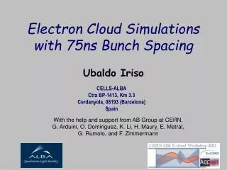
Witness Bunch Studies –e+ Tune Shift • Initial train of 10 bunches a generate EC • Measure tune shift and beamsize for witness bunches at various spacings • Bunch-by-bunch, turn-by-turn beam position monitor Positron Beam, 0.75 mA/bunch, 14 ns spacing, 1.9 GeV Operation Error bars represent scatter observed during a sequence of measurements (f=1kHzQ=2.5E-3) Preliminary BNL
Data and Simulation Overlay simulated EC density on vertical tune shift data • Initial comparisons for CESR • Growth modeling for dipole chambers Preliminary ECLOUD Program SEY = 1.4 Dipole Region BNL
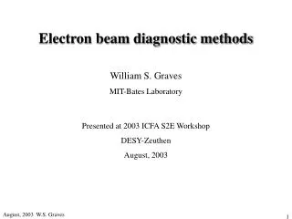
Witness Bunch Studies –e- Vertical Tune Shift • Same setup as for positrons • Negative vertical tune shift and long decay consistent with EC • Implications for the electron DR? Electron Beam, 0.75 mA/bunch, 14 ns spacing, 1.9 GeV Operation Negative vertical tune shift along train a consistent with EC Magnitude of shift along train is ~1/4th of shift for positron beam NOTE: Shift continues to grow for 1st 4 witness bunches! Preliminary Results BNL
EC Induced Instability • Vertical beam size along 45 bunch e+ trains (2 GeV, 14 ns bunch spacing) • Range of bunch currents • 200 50-turn averages collected for each point • Observe onset of instability moving forward in train with increasing bunch current – consistent with EC BNL
EC Growth Studies • Install chambers with EC growth diagnostics and mitigation • Goal is to have implemented diagnostics in each representative chamber type by mid-2009 • Heavy reliance on segmented Retarding Field Analyzers • Wiggler chambers in L0 straight w/mitigation • Dipole chambers in arcs w/mitigation • Quadrupole chambers w/mitigation • L0 and L3 straights • Drifts • Diagnostics adjacent to test chambers • Solenoids • Some components to be provided by collaborators L3 RFA Test Chamber BNL
Retarding Field Analyzers • Upgraded readout electronics for large channel count RFAs are in production • Thin RFA structure performing well Positron beam shadowed at test location BNL
Wiggler Vacuum Chamber Design CesrTA Electron Cloud Test Chamber 1 Assembly, 44mm Vertical Gap Hole Patterns for RFA Assembly Vacuum Tube, 4.00 OD x 3.50 ID Samples field node at boundary between poles “Postage Stamp” 1.0” x 1.7” Samples peak field in middle of main pole Samples falling field at quarter point of main pole (courtesy D. Plate, A. Rawlins, LBNL) BNL
CESR Dipole Chamber RFA RFA on Dipole VC Prototyping Underway BNL
First Beam Test of “Thin RFA” - First prototype “thin” RFA structure for wiggler chambers undergoing testing - First beam test shows performance similar to APS-style RFAs • Initial tests with 3mm test structure demonstrate key design aspects of the wiggler RFA • Calibration • Voltage test (no breakdown for DV = 600V) • Beam test • Detailed design underway for wiggler structure • Efficiency simulations to fully understand behavior in wiggler fields • Finalize structure by late January BNL
2 1 3 4 BNL
Experimental program • Cesr TA electron cloud program • 2008 • Install instrumented (RFA) dipole chambers (May) June • Electron cloud growth studies at 2-2.5GeV • Low emittance (~8nm) operation and alignment studies (Cesr-c configuration) July - August • Reconfigure CESR for low emittance (wigglers to IR) • Install wiggler chamber with RFA and mitigation hardware • Install dipole chicane • Optics line for xray beam size monitor • Extend turn by turn BPM capability to a large fraction of ring • Install spherical survey targets and nests and learn to use laser tracker Fall • Commission 2GeV 2.3nm optics [12 wigglers, CLEO solenoid off] • Survey and alignment • Beam based low emittance tuning • Characterize electron cloud growth with instrumented chambers Dependence on bunch spacing, bunch charge, beam size, beam energy • Explore e-cloud induced instabilities and emittance dilution • Commission positron x-ray beam size monitor (~2m resolution) BNL