Download
1 / 22
240 likes | 585 Views
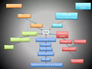
Clock Network Synthesis . Prof. Shiyan Hu shiyan@mtu.edu Office: EREC 731. Outline. Introduction H-tree Zero skew clock DME and its extension New trends. Introduction. For synchronized designs, data transfer between functional elements are synchronized by clock signals

E N D
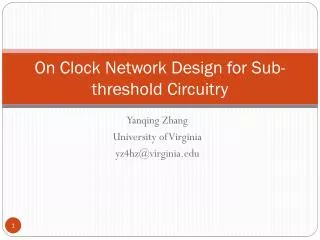
Clock Network Synthesis Prof. Shiyan Hu shiyan@mtu.edu Office: EREC 731
Outline • Introduction • H-tree • Zero skew clock • DME and its extension • New trends
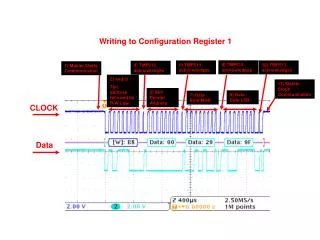
Introduction • For synchronized designs, data transfer between functional elements are synchronized by clock signals • Clock signal are generated externally (e.g., by PLL) • Clock period equation td: Longest path through combinational logic tskew: Clock skew tsu: Setup time of the synchronizing elements
Clock Skew • Clock skew is the maximum difference in the arrival time of a clock signal at two different components. • Clock skew forces designers to use a large time period between clock pulses. This makes the system slower. • So, in addition to other objectives, clock skew should be minimized during clock routing.
Clock Design Problem • What are the main concerns for clock design? • Skew • No. 1 concern for clock networks • For increased clock frequency, skew may contribute over 10% of the system cycle time • Power • very important, as clock is a major power consumer • It switches at every clock cycle • Noise • Clock is often a very strong aggressor • May need shielding • Delay • Not really important • But slew rate is important (sharp transition)
The Clock Routing Problem • Given a source and n sinks. • Connect all sinks to the source by an interconnect tree so as to minimize: • Clock Skew = maxi,j |ti- tj| • Delay = maxiti • Total wirelength • Noise and coupling effect
Clock Design Considerations • Clock signal is global in nature, so clock nets are usually very long. • Significant interconnect capacitance and resistance • So what are the techniques? • Routing • Clock tree versus clock clock mesh (grid) • Balance skew and total wire length • Buffer insertion • Clock buffers to reduce clock skew, delay, and distortion in waveform. • Wire sizing • To further tune the clock tree/mesh
Clock Source FF FF FF FF FF FF FF FF FF FF Clock trees • A path from the clock source to clock sinks
Clock Source FF FF FF FF FF FF FF FF FF FF Clock trees • A path from the clock source to clock sinks
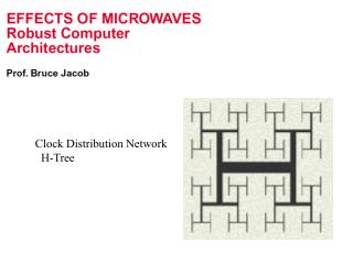
H-tree Algorithm • Minimize skew by making interconnections to subunits equal in length • Regular pattern • Can be used when terminals are evenly distributed • However, this is never the case in practice • So strict (pure) H-trees are rarely used • However, still popular for top-level clock network design • Cons: too costly is used everywhere
A Zero Skew Algorithm • Use Elmore delay model to compute delay • Try to minimize wire length, but not done very well • Lots of follow up works to minimize total wire length while maintaining zero skew • DME and its extensions
A Zero Skew Algorithm [Tsay’91] • This paper built the foundation for zero skew • Its principal can also be used to do prescribed skew (just solve a slightly different delay equation with non-zero skew) • However, its merging is kind of simple • May have too much total wire length
Deferred Merge Embedding • As its name implies, DME defers the merging as late as possible, to make sure minimal wire length cost for merging • Independently proposed by several groups • Edahiro, NEC Res Dev, 1991 • Chao et al, DAC’92 • Boese and Kahng, ASIC’92 • DME needs an abstractrouting topology as the input • It has a bottom-up phase followed by a top-down process
Bottom Up Phase • Each node v has a merging segment ms(v). • A merging segment is a Manhattan arc • Manhattan arc: has slope +/- 1 or has zero length (could be a point). • tiled rectangular region (TRR): The collection of points within a fixed distance from a Manhattan arc. • The intersection of two TRR’s is a TRR • Merging segments are always Manhattan arcs
DME Wrapup[Boese and Kahng, ASIC’92] • DME is guaranteed to find the minimum wire length with zero skew under the linear delay model • Need to have an abstract routing graph to start with
Modification: Bounded Skew • Instead of choosing merging segments as in DME, choose merging region of v, mr(v) • Maintains skew bound • Use boundary merging and embedding which considers merging points lying on the nearest boundary segments of mr(a) and mr(b)
Topology Generation • One common approach • Balanced and geometry guided • Top down-partitioning that recursively divide the set of sinks, using alternating horizontal and vertical cuts • The balance bipartition heuristic generates a topology that recursively divides the set of sinks into two subsets with equal total loading capacitance • Balanced tree versus unbalanced tree? • Geometric versus capacitive load? • [Chaturvedi and Hu, ICCD’03] has good survey of recent works • Abstract topology not just geometric, but also capacitive load, with prescribed skew
Trend • Clock skew scheduling together with clock tree synthesis • Schedule the timing slack of a circuit to the individual registers for optimal performance and as a second criteria to increase the robustness of the implementation w.r.t. process variation. • Variability is a major concern • Non-tree clock, mixed mesh/tree? • How to analyze it? • The task is to investigate a combined optimization for clock skew scheduling and clock tree synthesis such that any unintentional clock skew is maximally compensated by a corresponding slack at the registers. (P. Restle)