Download
1 / 11
110 likes | 232 Views
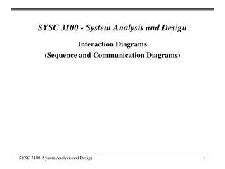
Special Case – Ray Diagrams. AP Physics B. What if the object is ON “f “ ?. f. f. If the object is ON the focal point, no image is produced as there is NO intersection. C. f. Principal axis. Converging Lens – Inside of “f ”. f. f.

E N D
Special Case – Ray Diagrams AP Physics B
What if the object is ON “f “ ? f f If the object is ON the focal point, no image is produced as there is NO intersection. C f Principal axis
Converging Lens – Inside of “f ” f f When object is inside of “f”, extend the 2nd line of the rule, BACKWARDS! This image is VIRTUAL, ENLARGED, and UPRIGHT
Converging Lens – Inside of “f “ Suppose we have an object placed 15 cm in front of a converging lens (f = 20 cm). Calculate the image position and characteristics. f f -60 cm 4x As we thought. The image distance is negative, thus making it a VIRTUAL image. The magnification was positive and greater than 1, making it enlarged and upright. This is a MAGNIFYING GLASS!
Converging Mirror – Inside of “f “ f C The image is VIRTUAL, ENLARGED, and UPRIGHT. This is a compact mirror!
Diverging Lens f f The image is VIRTUAL, REDUCED, and UPRIGHT. On the next slide we will verify with the math. But before we do it is important to understand that all DIVERGING LENSES AND MIRRORS have NEGATIVE FOCAL LENGTHS!!!.
Diverging Lens f f Once again, the image is verified as VIRTUAL as the image distance is negative. The image is verified using the magnification formula to be UPRIGHT and REDUCED. 0.36x -12.73 cm
Diverging Mirror f C The image produced is VIRTUAL (it is on the OPPOSITE side) and REDUCED and UPRIGHT. This could be back end of a spoon, a Christmas tree ball ornament, an anti-theft mirror in a store.
Dual – Lens or Mirror-Lens There are certain circumstances where you may have TWO optical devices to deal with such a dual lens or perhaps a Mirror and a Lens. Lets look at the Mirror-Lens situation. You draw the ray diagram normally except that the image from the first optical device becomes the object for the second. Suppose we have a converging lens in front of a diverging mirror with an object to the left of the lens f f f C The final position of the image appears to be inside the “f” of the mirror, VIRTUAL, REDUCED and INVERTED. We really need to apply the optics equations to verify our picture.
Example Suppose in our previous slide we place an object 44 cm in front of a converging lens (f = 22 cm). A diverging mirror ( f = -22 cm) is then placed 50 cm to the right of the lens. Calculate the FINAL images position and characteristics. 70 44 cm The object distance for the mirror is 50 cm minus 44 cm, or 6 cm 44 cm -1x
Example You might think that since the second magnification was positive that the image would be upright. Keep in mind that everything is RELATIVE to the object. Since the object was inverted so was the image despite getting a positive magnification. 0.769x -4.62 cm (-1)(0.769)= -0.769x So the FINAL image is VIRTUAL, INVERTED, and REDUCED..relative to the original object.


![Shear Force and Bending Moment Diagrams [SFD & BMD]](https://cdn3.slideserve.com/6594612/shear-force-and-bending-moment-diagrams-sfd-bmd-dt.jpg)