Download
1 / 11
110 likes | 396 Views
Internal Combustion V-8 Engine. Team #3 Marco Mendoza Carlos Diaz Kevin Tevis John Harrison Wilfredo Rodriguez Bill VanFossen. Otto cycle. Adiabatic 4 step process. Intake – piston moves downward, creating a vacuum which forces the air fuel mixture into the cylinder.

E N D
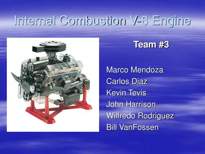
Internal Combustion V-8 Engine Team #3 Marco Mendoza Carlos Diaz Kevin Tevis John Harrison Wilfredo Rodriguez Bill VanFossen
Otto cycle • Adiabatic 4 step process Intake – piston moves downward, creating a vacuum which forces the air fuel mixture into the cylinder. Compression – Piston reaches bottom dead center and the intake valve closes. Piston begins to move to top dead center. Power – piston reaches top dead center and spark plug ignites air fuel mixture causing a combustion which forces piston back down. Exhaust – piston reaches bottom dead center, exhaust valve opens, piston moves back to top dead center, forcing exhaust out of cylinder.
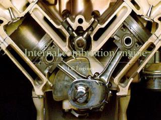
V-8 Internal combustion engine • Carbureted • Eight cylinders • 16 valve push rod • Piston orientation 90 degree apart • Hemispherical combustion chamber • Single over head cam design (SOHC)
Increased Horsepower due to 8 combustion chambers. Increased torque due to longer stroke Power conservation: Push rod driven engines do not deplete power as in the belt driven designs. Less complex (SOHC design) High packing efficiency compared to inline engine Carburetor not as fuel efficient as fuel injectors Heavy In comparison to other valve trains, push rods are not as efficient. More emissions Advantages of V8 Disadvantages of V8
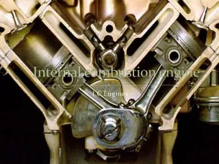
Cylinder Block assembly • Typically cast from iron or aluminum • Encases crankshaft, connecting rods, pistons. • Main structural component of engine, responsible for driving flywheel and other components of vehicle.
Crankshaft • Comprised of eight counterweights • Converts vertical motion of pistons to circular motion of shaft, which drives the flywheel and eventually the wheels of the vehicle. • Attached to the Flywheel and the timing gear • Connecting rod is fixed to the crankshaft by the main bearing cap.
Cylinder head • Encases the camshaft, valves, pushrods, and rocker assembly. • Connected to the intake and exhaust manifold. • Typically cast from iron or aluminum • Together with the head gasket, a seal is formed that allows for high compression
Valve train • Composed of valves, camshaft, rocker arms, rocker shafts, pushrods. • Allows engine to “breath” when in sync with crankshaft rotation (responsible for all strokes).
Challenges • Timing and firing order • 32 valve/rocker/cam connections • Complex cylinder head design • Manufactured pieces inconsistent with model (pieces didn’t fit together) • Cheap plastic model • Dimensions difficult to measure • Model design inconsistent with actual V8 engine design.
Possible Improvements • Spring-less valve trains: Friction losses and spring forces can reduce engine output up to 25%; possible solutions are solenoids and desmodromic valves. • Fuel Injection system: Produces more power than carbureted engine. Also results in better fuel efficiency and less emissions.