Download

1 / 26
510 likes | 1.74k Views
Wave Equation Applications. 2009 PDCA Professor Pile Institute. Patrick Hannigan GRL Engineers, Inc. Analysis Types. Bearing Graph - Proportional Resistance (most common) - Constant Shaft (i.e. pile driven to rock) - Constant Toe (i.e. friction pile)

E N D
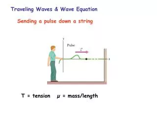
Wave Equation Applications 2009 PDCA Professor Pile Institute Patrick Hannigan GRL Engineers, Inc.
Analysis Types Bearing Graph - Proportional Resistance (most common) - Constant Shaft (i.e. pile driven to rock) - Constant Toe (i.e. friction pile) Analysis Results: Capacity, stress, stroke (OED) vs. Blow count Analysis Application: Hammer approvals, capacity assessments, hammer sizing.
Analysis Types Inspector’s Chart • For a constant capacity (e.g. the required ultimate capacity), plots stroke vs blow count • Variable energy hammers only • Single acting diesel (open end) • Double acting diesel (closed end) • Single and Double Acting Hydraulic hammers • Primarily used for field control • For an observed hammer stroke, what is minimum blow count?
Analysis Types Driveability User inputs detailed soil profile including expected soil strength losses, splice depths, wait times, etc. GRLWEAP calculates soil resistance and associated numerical results at user specified analysis depths. Analysis Result: blow count, stresses, and transferred energy versus depth Analysis Interpretation: predicted blow counts and stresses allow determination of driveability through problematic dense layers Application: frequently used in the offshore oil industry
Summary of Wave Equation Applications Develop Driving Criterion Blow Count for a Required Ultimate Capacity Blow Count for Capacity as a Function of Energy / Stroke Check Driveability Blow Count vs. Penetration Depth Driving Stresses vs Penetration Depth Determine Optimal Driving Equipment Driving Time Refined Matching Analysis Adjust Input Parameters to Fit Dynamic Measurements
REQUIRED INFORMATION • Hammer • Model • Stroke and Stroke Control • Any Modifications • Driving System • Helmet Weight (including Striker Plate & Cushions) • Hammer Cushion Material (E, A, t, er) • Pile Cushion Material (E, A, t, er)
REQUIRED INFORMATION • Pile • Length, • Cross Sectional Area • Taper or Other Non-uniformities • Specific Weight • Splice Details • Design Load • Ultimate Capacity • Pile Toe Protection
REQUIRED INFORMATION • Soil • Boring Locations with Elevations • Soil Descriptions • N-values or Other Strength Parameters vs Depth • Elevation of Excavation • Elevation of Pile Cut-off • Elevation of Water Table • Scour Depth or Other Later Excavations
Ram Anvil Pile Driving and Equipment Data Form
GRLWEAP Example 1 & 2 Problem Ru = 330 kips
GRLWEAP Example 1 Solution - SI 195 MPa 1480 kN 2.6 m 68 blows / 0.25 m
GRLWEAP Example 6 Problem Hammer: ICE 42-S: 56.9 kJ (42 ft-kips) or Vulcan 014: 56.9 kJ (42 ft-kips) Hammer Cushion: Varies Helmet: Varies Depth (m) (ft) 0 0 Pile: Closed End Pipe Pile Length 20 m (66 ft) Pile Penetration 16 m (52.5 ft) 355 mm (14 inch) x 9.5 mm (3/8 inch) Ultimate Capacity 1800 kN (405 kips) 10 4 Loose Silty Fine Sand 20 8 30 Shaft Resistance, 30% Triangular Distribution 540 kN (121 kips) 12 40 50 16 Very Dense Silty Fine Sand Toe Resistance, 70% 1260 kN (284 kips) 60 20
GRLWEAP Example 8 Solution - SI 7.1 mm 6.3 mm
GRLWEAP Example 8 Solution - SI 9.5 mm 7.9 mm
GRLWEAP Example 8 Solution 9.5 mm 7.9 mm Criteria 0.90 FY = 279 MPa or 40.5 ksi, Blow count of 25 – 98 bl/.25 m or 30 - 120 bl/ft