Download
1 / 43
440 likes | 664 Views
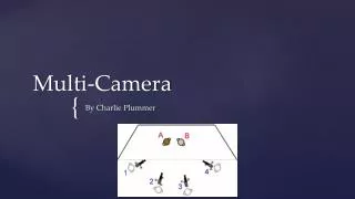
Multi video camera calibration and synchronization. Motivation. Multi camera applications become common. Example: Stereo, Surveillance … . Using multi camera we can over come problems like hidden objects. In general more cameras equal more information on the scene. How does it look.

E N D
Motivation • Multi camera applications become common. Example: Stereo, Surveillance…. • Using multi camera we can over come problems like hidden objects. • In general more cameras equal more information on the scene.
How does it look • Multi camera setup
The scene • The filmed scene 1/3
The scene • The filmed scene 2/3
The scene • The filmed scene 3/3
Perspective projection Perspective projection:
The projection matrix • Object point • Image point • Using the model: • And the projection matrix (so far) is: *Homogenous coordinates
Internal matrix • The internal matrix represent the inner camera settings • Focal length (d) • Principle point location usually (0,0) • Scaling factor
External matrix • Includes all the orientation properties of the camera • Rotation • Translation
Projection matrix sum up • Internal parameters • External parameters • The result p=MP
Calibration • Camera calibration is used to coordinate between cameras. • Given a 3D point in the real word finding the projected point in the camera. • The goal is to fined the projection matrix M. • Using known 3D points and there corresponding image points p=MP can be solved.
When a full calibration is not necessary Homography • Mapping between a point on a ground plane as seen from one camera, to the same point on the ground plane as seen from a second camera.
When an Homography can be used • When the images are of the same plane Camera 1 Camera 2 Result
When an Homography can be used • When images taking using same camera by only rotating it
Homography computation • Using the Homography matrix H we can map point from one image to second image • So we have : p’=Hp • P and p’ are given in homogeneous coordinates
Homography computation • H is 3x3 • That is 8 D.O.F • To find H we need 4 corassponding points
Finding corresponding points • Manually, detecting by hand similar features. • Not accurate • Good for 2 cameras, what about 9 or more.
Known solution • Automatic Detection of known features. • Large working volume need large objects. • very hard to detect from far distance.
Features detection in wide base line • Noise • Hidden parts • Assuming detection is possible finding the corresponding is hard.
Goals of the calibration object • 360 degrees view. • Robust to noise. • Accurate regardless the distance (or zoom). • Easy to find corresponding points. • Automated as possible.
Solution • Use easy to detect features (Active features). • Use the benefits of time dimension video. • This will create a easy to detect corresponding point list. • Find Homography using the list of points.
Calibration object • Ultra bright LEDs. • Very bright, easy to detect.
Use flickering as identifier • features flicker in constant rate • Each feature has a different rate • The cameras filming in constant rate • The LED flicker can be found • The result a list of points in an increasing frequency rate for each camera
Detection method first stage • Filter unnecessary noise • Use the red channel only as filter. • What about acceptable red channel filters in RGB such as:R = ((R-B)+(R-G)). • Remove white pixels (All channels have high intensities ). • Not good for a case a LED caused high saturation (appears as white).
Filter Example • Red channel only((R-B)+(R-G))
Detection method second stage • Take advantage of video camera time line • The LED is going from on to off state • Subtracting following frames (similar to background subtraction). • Detect features pixels candidates using a threshold. • Save detection frame number to detect flickering rate.
Detection method third stage • So far we have points candidate and there frequencies. • Yet some of the candidates are noise. • Use a frequency as a second filter • Most of the noises have a very short and not consist frequency.
Noise and feature frequencies • Noise • Feature
Frequency filter • Before
Frequency filter • After
Detection method fourth stage • Once we have the LED pixels detected we need to detect a pixel to represent it • Local maximum, the pixel with the highest intensity level. • Solution to different distances of camera from the features and different zoom rates.
Local maximum example • Before
Local maximum example • After
Synchronization • Given the frame number k in the first camera find the corresponding frame in the second camera. • Not all the cameras starts to film in the same time. • Known solution using temporal features
Temporal features • Hard to find, not suitable for 9 cameras or more
Automatic synchronization • Each feature has a different rate • The signature is based on the gap between the pools vibrate. • Given an index we search for the first time after this index the pool with the lowest frequency vibrate and so on. • Given that the polls turned on in t0,t1,t2,t3,t4,t5 the resulting signature is • (t1-t0,t2-t1,t3-t2,t4-t3,t5-t4)
The end • Thank you!!!