Download
1 / 57
1.02k likes | 1.54k Views
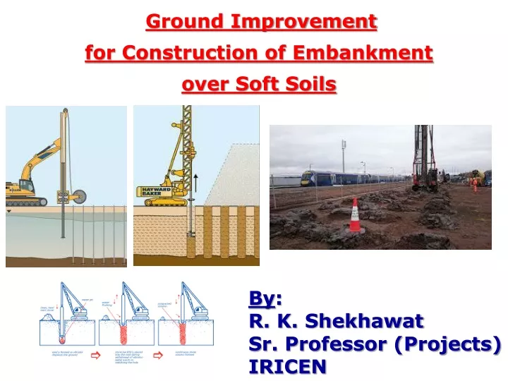
Ground Improvement for Construction of Embankment over Soft Soils. By : R. K. Shekhawat Sr. Professor (Projects) IRICEN. 1. Soft Soils Highly Plastic, Fine grained soils with moderate to high clay fraction. It is usually CH/MH type. 2. Geotechnical Properties of Soft Soils

E N D
Ground Improvement for Construction of Embankment over Soft Soils By: R. K. Shekhawat Sr. Professor (Projects) IRICEN
1. Soft Soils • Highly Plastic, Fine grained soils with moderate to high clay fraction. • It is usually CH/MH type. • 2. Geotechnical Properties of Soft Soils • % Fines (passing through 75 Sieve) > 50% • High Liquid Limit (>50%) & Plastic Limit (>25%) • High Natural Moisture Content • Low Material Permeability • Low shear strength, varies with depth: • Undrained Shear Strength < 12 kPa – Very Soft Soil • Undrained Shear Strength < 25 kPa – Soft Soil • Highly compressible, Organic content increases it.
3. Drained and Un-drained Shear Strength • When a Fine Grained Saturated soil is rapidly loaded (this rapid loading may be over several months during construction period), excess pore water pressure is generated. • Excess pore water pressure gets dissipated over a period of time, which in case of clay deposits may extend for many years. • This is called process of “Consolidation”. Provisions of GE:G-14 • If Ev2 < 20 Mpa or Cu < 25 kPa or N value less than 5 • Sub-soil/ground has to be improved for: • Reducing consolidation time & settlement; • Increasing bearing capacity/shear strength of sub-soil.
Shear Strength Terzaghi's Theory Ʈf = C + σ tan Ø Ʈf = Shear Strength of Soil C = Cohesion Intercept σ = Normal Stress in the plane of failure Ø = Angle of Internal friction Ʈf = C’ + (σ- u)tan Ø’ C’ = Effective Cohesion Intercept u = Excess Pore Water Pressure Ø’ = Effective Angle of Internal friction
4. Occurrence of Soft soils in India • Marine Deposits Area • River Delta Deposits Areas • Area of Gulf of Kutch • Shores of Gulf of Cambay • East Coast • West Coast • 5. Problems in Construction on soft soils • Low initial un-drained Shear Strength • Stability of Embankment • High Compressibility and Settlement of Embankment
7. Engineering Techniques for Ground Improvement Pre-loading Vertical Drains Stone Columns Geo-synthetics Dynamic Consolidation
7.1 Pre-loading Method Economical Method for accelerated construction, especially when compressible layer is of lesser thickness. The fill material can be used for construction. This technique alone may not be efficient as it requires very long time for consolidation. Pre-loading can be in two forms: Over Loading Stage Construction Methods
7.1.1 Over Loading Method • A surcharge (overload) is placed on the soft ground. • After a pre-determined time lapse, the bank can be built. • Magnitude of surcharge and its’ Duration of placement are determined by conventional settlement calculations.
7.1.2 Stage Construction Method Construction of high bank over soft clays can be done in single stage only with very flat slopes or with wider sub-banks, which is highly uneconomical. Stage construction and Observational method is a solution to this problem. In this method, advantage is taken of increase is shear strength of sub-soil due to consolidation by surcharge loading.
7.2 Vertical Drains 7.2.1 Sand Drains 7.2.2 Sand Wicks 7.2.3 Cardboard Drains 7.2.4 Synthetic Drains
7.2.1 Sand Drains A column of 20-30cm dia is augured into the ground to be surcharged and consolidated. The column is then filled with sand and connected to a free draining blanket of granular layer.
Sand wicks are ready made small diameter sand drains pre-packed in filter stocking. • In early days, woven jute canvas was used as filter stocking, but presently polypropylene woven and melt bonded fabrics are used. 7.2.2 Sand Wicks
They are inserted into the ground by means of a mandrel which is then removed. • Channels in the cardboard facilitate the removal of water. • They are easy to install and cause little soil disturbance. • The specially processed cardboard has a long life and are quite durable. 7.2.3 Cardboard Drains
Pre-fabricated Vertical Drains (PVD) are typically 95-100 mm wide by 3-5 mm thick. Synthetic core is wrapped with geo-textile. • Less bulky and easier to handle. But, require sophisticated installation techniques. • Their installation causes little disturbance to the neighbouring soil and are over sand drains. Large settlements of substrata do not destroy the drain continuity. • Usually installed by displacement method. The mandrels used are hollow and rectangular or trapezoidal in cross section. 7.2.4 Geo-synthetic Drains
7.2.4 Geo-synthetic Drains (PVD) Animation Execution
PVD Case History -1 Sub-Soil Stabilization over Ennore Creek for 3rd & 4th line between Korukkupet-Attipattu in Chennai-Gudur section, Southern Railway during Aug-Dec’08 • It was very difficult to construct the bank in normal manner and project would have been delayed by 5-6 years. • To avoid shear failure of the embankment, a geo-textile layer was provided on the top of existing ground level.
PVD Case History - 2 Udaipur Station Yard in Tripura State of N. F. Railway • Construction of Embankment (6.2m Height) started in Dec’2010, without any Ground Improvement. • Number of failures of embankment, at height of 3-3.5m, between Sept’2011 to Dec’2012, with heaving up to 30m distance from toe of bank. • Detailed Geotechnical and Hydrological Investigations done – Site of construction is a lake with water level during monsoon going 3-4m above EGL. Soft Clay up to 9-13 m from EGL. • Consultancy taken from IIT/Guwahati: • Strip the embankment constructed and re-build with appropriate Ground Improvement measures.
PVD Case History - 2 • Owing to time constraints and non-availability of stone aggregates nearby, PVD would be suitable measure for Ground Improvement. • PVD in triangular pattern, with Spacing of 0.8m c/c. 150mm Coarse Sand layer above PVD, with top of PVDs in this layer. Over this, a layer of non-woven geo-textile and on top of it 300mm thick layer of coarse granular material. A layer of woven geo-textile over the granular layer. • Stage construction, with sufficient time between each stage. Monitoring of Settlements using “Plate Type Settlement Gauges” and Pore water Pressure with “Casagrande Type Piezometers”. • 95% Consolidation calculated to take 100 days. Total settlement calculated to be 1242mm.
PVD Case History - 2 • Proper berms, drainage system and slope protection for re-built embankment. • Advisable to build entire station area up to 2m height before reaching full embankment height. • Work completed successfully.
PVD Case History - 3 Between Vaikom Road – Kuruppantara (Km 36/700 - 37/000) in Ernakulam – Kottayam - Kayankulam Doubling, Southern Railway) • Located on Vaikam Road side approach of Kaduturthy River Bridge, with height of existing embankment about 3m and height of new embankment about 5m. • Up to 6m depth, sub-soil is “Sandy Clayey Silt” with N Value from 8 to 12. Allowable Safe Bearing Pressure is 4 T/m2 at 1.5m depth and 12 T/m2 at 6m depth. • On construction of full height of new bank, there was failure of new bank with heaving of ground on vacant land. • The fill material was removed completely and Technical Consultancy was taken, which was checked & approved by of IIT/Madras.
PVD Case History - 3 • Recommendations in Consultancy Report : • PVD at 0.8m c/c spacing in triangular pattern. After PVD installation, providing drainage filter and laying high strength geo-textile at the base, construct embankment for 3.5m height in Stage-1. • After 70% consolidation (in about 1.5 months), raise embankment to final height in Stage-2. • Degree of consolidation achieved in stage construction shall be evaluated using actual settlement data and pore pressure data recorded at the site. • Bank was constructed successfully with monitoring of Settlement by “Platform Type Settlement Gauges” and Pore Water Pressure by “Casagrande Piezometers”.
PVD Case History - 3 • After construction of full height of bank, settlements were recorded at four locations and they have stabilized.
PVD Case History - 4 Between Vaikom Road – Kuruppantara (Km 37/200 – 37/700) in Ernakulam – Kottayam - Kayankulam Doubling, Southern Railway) • Located on Kurappnatara side of Kaduturthy River Bridge, with height of existing embankment about 5.5m and height of new embankment about 7.5m. • Up to 3m depth, sub-soil is “Sandy Clayey Silt” with N Value from 11 to 48. Allowable Safe Bearing Pressure is 11 T/m2 at 1m depth and 50 T/m2 at 3m depth. • On construction of new bank for about 4m height, there were failures at km 36/875 and km 36/800 with heaving of ground on vacant land. • The fill material was removed completely and Technical Consultancy was taken, which was checked & approved by of IIT/Madras.
PVD Case History - 4 • Recommendations in Consultancy Report : • PVD at 0.8m c/c spacing in triangular pattern. After PVD installation, providing drainage filter and laying high strength geo-textile at the base, construct embankment for 3.5m height in Stage-1. Construct a berm of 3m width and 2.5m height. • After 70% consolidation (in about 1.5 months), raise embankment to final height in Stage-2. • Degree of consolidation achieved in stage construction shall be evaluated using actual settlement data and pore pressure data recorded at the site. • Bank was constructed successfully with monitoring of Settlement by “Platform Type Settlement Gauges” and Pore Water Pressure by “Casagrande Piezometers”.
PVD Case History - 4 • After construction of full height of bank, settlements were recorded at two locations and they have stabilized.
7.3 Stone Columns • Consists of well graded/granular material having high angle of internal friction/ chemically inert/hard/preferably angular in shape. • A large portion of applied load is initially resisted by relatively strong stone column and remainder by cohesive soil. • Variation in load sharing takes place till strains in both material achieve compatibility and equilibrium conditions are attained. • They interact with soil, increasing shear strength & decreasing compressibility of soil. • Also act as drain, accelerating consolidation settlements and minimizing post-construction settlement.
Animation 7.3.1 Vibro Floatation Technique Execution
Stone Column - Case History Keshabpur – Mahisadal Stations in Panskura – Haldia doubling, in S. E. R., executed by RVNL • Average Height of new embankment is 9m and 30m away from entre line of existing track. • Earthwork was done up to 3.5m height at Ch. 7270-7720, in year 2011-12, and this patch was used as access in the block section. • Top width of bank was 6.85m, with 2H:1V Side Slope up to 6m height. Above 6m, height a 3m wide berm was provided with 2.5H:1V Side Slope below berm. • In year 2013-14, balance height of bank and blanketing was done in about 3 months time. Major subsidence of bank (with base failure) at Ch. 7220-7500 (on 03/04.04.2014) and Ch. 7500-7720 (on 06.05.2014), causing heaving by 1.25m on side.
Stone Column - Case History • On detailed investigation, the cause was found to be “fast pace of construction, which did not allow the pore pressure in sub-soil to dissipate, resulting into base failure”. • Sub-soil Investigation:
Stone Column - Case History • The filled-up area was a water body (pond). The water table in the area is just 1m below the EGL. • Similar problem was faced during construction of Single Line in year 1969. At that time, very wide bank profile was adopted and Cinder/Steam Loco Ash (Granular Material) was used as fill material. • Technical Consultancy was taken. Recommendations of this consultancy were verified by Independent Consultant Shri R. R. Jaruhar, ex. ME. RDSO was also involved in finalizing construction scheme. • Pre-loading takes longer time and PVD was found unsuitable due to very poor bearing capacity of he sub-soil. Hence, use of Stone Column was found to be most suitable.
Stone Column - Case History • Final recommendations: • Stone Columns 600mm Dia, @1.6m c/c for bank height up to 6m and @2m c/c for bank height above 6m, in Square Grid pattern, up to 5m beyond the toe of embankment. • 0.5m thick Drainage layer of Sand, extended up to 50 cm beyond the toe of bank. • Side Slope of 3H:1V • Berm of 3m width, after 4m bank height from top • Filling up of pond area near toe of bank, up to (H+3)m distance from toe of bank. • Turfing on bank with cross slope drains on bank slope, at 50m c/c spacing.
Stone Column - Case History • Effectiveness of Stone Columns checked by Plate Load Test as per IS 15284 (Part-I):2003
Stone Column - Case History • Primary Consolidation Settlement was calculated as 163mm and Secondary Consolidation Settlement was calculated as 73mm. • Actual Primary Consolidation Settlement and Secondary Consolidation Settlement did not stabilize even at values of 175mm and 85mm respectively also. • Surface Settlement gauges (8 nos.) were installed, at 3m from centre of line of proposed track. Settlement readings were taken thrice a week, till they stabilized. • The section was inspected by CRS on 26.11.2015 and Speed Trial with 115 kmph completed satisfactorily.
7.5 Dynamic Consolidation • Repeated dropping of 10-40 T Weight on the ground surface from 10-40m height, with well defined pattern of time and spacing of drops. • Effective for loose sands, soft clays and peats. • Suitable for large sites. • The soft soil is overlain by a working platform of granular soil. • Horizontal drains are provided to drain out water rising to surface due to dynamic consolidation. • Vibrations of impact may prohibit use of this technique in urban areas.
8. Important Aspects for Consultancy Proper presentation of problem to the Consultant with Railway's requirements: Required FOS – 1.2 (Short Term/End of Construction) and 1.4 (Long term). Effect on existing bank. Study of Consultant’s recommendations before their implementation, including explicit check about Stage Construction. Ground Improvement measures (PVD, Stone Column etc.) to extend beyond toe of embankment (by about H/3 to H/2). No Pond/Ditch within (H+3)m beyond toe of Embankment.
9. Instrumentation and Monitoring Design of embankment is done with available field and lab data of soil. Prediction of response of embankment and sub-soil is based on design assumption and soil parameters. It may not be accurate. Hence, monitoring of critical parameters like Pore water pressure, Settlement etc. is very essential. Comparison of predicted and actual performance during construction and taking corrective action required, well in time.