Download
1 / 27
270 likes | 495 Views
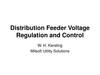
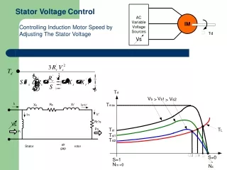
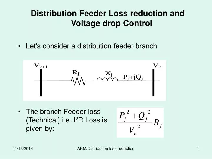
Distribution Feeder Loss reduction and Voltage drop Control Let’s consider a distribution feeder branch. The branch Feeder loss (Technical) i.e. I 2 R Loss is given by:.

E N D
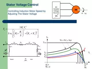
Distribution Feeder Loss reduction and Voltage drop Control • Let’s consider a distribution feeder branch The branch Feeder loss (Technical) i.e. I2R Loss is given by: AKM/Distribution loss reduction
In case of transmission line, the line carry same P and Q over a longer distance and just for a line thus is very easy to compute. • In a distribution line (whether a primary or secondary) The P and Q along the feeder do not remains the same. Hence the loss even for a single feeder is represented as: AKM/Distribution loss reduction
From the above expressions for the minimum Loss and voltage drop: • Pj to be minimum • Qj to be minimum • Rj to be minimum • Xj to be minimum • Vk to be maximum • Fortunately all of these three are possible for distribution system. AKM/Distribution loss reduction
Branch power to be minimum • For minimum loss and voltage drop; • As far as possible, the branch Real and Reactive power flow for each branch should be minimum • May not be possible in all cases • At least the considerations to the branches carrying relatively higher powers. • This can be achieved by • Optimum configuration (for planning decisions) • Reinforcement (for existing system) • Reconfiguration (operational decisions) • Addition of Real and reactive powers sources along the distribution feeder (Distributed generator/Reactive compensation) AKM/Distribution loss reduction
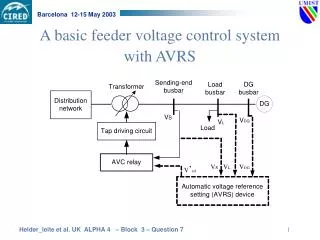
A Primary distribution network shown below the load at each buses has increased significantly that from the planning and hence the losses are high. • It is desired to explore the viable options to improve the voltage profile and loss reduction • The idea is technically viable and economically best • Out of many options one option could be; • Disconnecting the T1- T5 line at T1 and connecting T1 to the S/S with a new Feeder. (reducing P &Q between S/S-T1) • Second option could be change the conductor between S/S to T1 (reducing resistance) AKM/Distribution loss reduction
Let's consider five different distribution transformers of same size and same number of customers are desired to be connected from the substation through a radial distribution feeder of similar conductor. Out of practically feasible feeder layout options two are shown in Fig.(a) & (b). • The load to be served in both the cases same • Conductor length same • But it can be shown that the losses in option – A is about 1.5 times greater than option-B AKM/Distribution loss reduction
Suppose the transformer size at each of the node is S kVA. Then the power flow through the branches can be easily computed and is shown in Fig. below. AKM/Distribution loss reduction
It is to be noted that this difference in losses are only due to the fact that the branch power to serve the same load are significantly different in two options. • Alternatively it can be said that the node powers have to travel larger distance in option-A than option-B. Summarized in Table below: The idea is; To configure the feeder in such a way that the distance of all the load points to source should be minimum. AKM/Distribution loss reduction
Different nodal demands and conductors • If the load at different nodes are different then; Should be minimum. • Where: • Si Demand at ith Node • Li distance of ith Node from S/S • If the conductor in the path is also different then; • Where: • j represents the branch in ith path and • xj length of jth branch • and rj p.u. length resistance of jth branch AKM/Distribution loss reduction
Reactive Power Flow: AKM/Distribution loss reduction
The Source of reactive power are shown by arrow and demand of reactive power is at A, B and C. • So for Minimum loss it is very easy to say that reactive power for B and C should come from Capacitor and for A it should from S/S. • Hence the Size of the Capacitor for Minimum Loss is 120 kVAR. AKM/Distribution loss reduction
Optimal Capacitor Placement • Capacitors are often installed in distribution system for reactive power compensation to carry out • power and energy loss reduction, • voltage regulation improvement • system capacity release, and • system security improvement . AKM/Distribution loss reduction
Capacitor can reduce the loss mainly due to reactive component of line (branch) flow. • Ideally speaking capacitors should be placed at each and every load center so that the losses due to reactive component of line flow is zero • Practically it is not possible due to higher installation cost • Since the demand at load centers vary with time, requires not only the capacitor to be located but should be controlled requiring higher accessories cost as well AKM/Distribution loss reduction
Capacitors at HT or LT • If capacitors are placed at LT • Loss will be minimum at both HT and LT • Requires switching operations necessitating expensive switchgear • The provision of LT capacitors on the individual services usually having low power factor is generally preferred. • The capacitors are placed normally on HT only at some optimal locations with optimal sizing and control switch gear. AKM/Distribution loss reduction
The optimal capacitor placement is the determination of the location and size of the capacitors to maximize the saving i.e. maximization of equation: AKM/Distribution loss reduction
In fact, it is required to obtain the number of optimal capacitor locations their locations and size of the capacitors simultaneously to give the best result. • We can think the size of the problem if we consider the each possible options. • Some advance techniques such as AI based techniques (ANN, GA) have been applied which are capable to give the global optimum solution. • Several classical approach have also been used which (all of these) try to give the optimum solution as far as possible minimizing the computations. • This of course make same valid assumptions to simplify the problem • Here we are discussing one of such classical iterative procedure to determine the optimal location and sizes AKM/Distribution loss reduction
The overall procedure is further simplified first finding the expression for power loss reduction for a set of capacitors located optimally. • Later an iterative procedure is employed to update the locations one by one. • The number of capacitor locations are then identified for which the overall saving is maximum this is possible with the inclusion of fixed cost in objective function • Before going to the detail procedure first consider the correlation of loss reduction with: • Capacitor(s) location • Capacitor(s) Size • To understand this, Let’s consider a section of distribution system AKM/Distribution loss reduction
The expression for power loss reduction In the matrix form can be written as; = -[Ic1 Ic2 Ic3] r1+r3 r1 r1 Ic1 r1 r1+r2+r4 r1+r2 Ic2 r1 r1+r2 r1+r2 Ic3 Ic1 +2[(r1Iq1+r3Iq3) (r1Iq1+r2Iq2+r4Iq4) (r1Iq1+r2Iq2)] Ic2 Ic3 = -IcT H Ic +2b Ic AKM/Distribution loss reduction
The square matrix H and vector b can be easily be found from known feeder configuration and capacitor location Hii= sum of branch resistances from source to ith capacitor location Hij= sum of branch resistances from source to the node where ith capacitor location and jth capacitor locations diverges bi= sum of the product of reactive component of current and branch resistances from source to ith capacitor location • The size of H matrix is ncap x ncap and the size of the b vector is also ncap • For maximum Loss reduction, the derivative of LPq w.r.t. Ic should be zero. This Results the size of capacitors as: Ic(optm) = H-1b Thus the peak power loss reduction with this capacitor power Loss reduction can be calculated as: LPq= - Ic(optm)T H Ic(optm) +2b Ic(optm) AKM/Distribution loss reduction
The overall procedure • There are mainly two schemes that are repeated successively and the process stops when the choice of locations can not contribute further improvement. Scheme-I: • In this scheme, for a known set of location, capacitor sizes are found for maximum loss reduction i.e. Ic = H-1b Scheme-II: • In this scheme, relocations and sizing of one capacitor is done assuming that the rest of the (ncap – 1) capacitors are already placed and sized. • If suppose kth capacitor is to be relocated and sized, the problem reduces to placement and sizing of a single capacitor. • For this first the load current distribution is modified to consider the ncap-1 capacitors are negative loads • Then for each possible locations of kth capacitor the optimal size Ici = bi/Hi. AKM/Distribution loss reduction
Read system parameters and assume a suitable number of capacitors and their initial set of locations. • Apply scheme-I to get the sizes. • Set iteration number 1. • Perform scheme-II to relocate each capacitor for each capacitor locations individually (i.e. ncap times) • Apply scheme-I to improve the sizes for complete set of location and compute the power loss reduction. • Repeat steps 4 & 5 till the choice of locations can not contribute further improvement. AKM/Distribution loss reduction
Optimal Number of capacitor locations • The procedure described till now is for known number of capacitor locations. • As we already discussed the cost of capacitor also depends on at how many places we put this. • Usually in a primary distribution feeder even consisting of several nodes the number of capacitor location is very few e.g. maximum not more than 4 or 5. • Thus the procedure described earlier could be repeated for number staring from 2 and find the optimum location and sizes for each number and computing the saving for each number • To simplify the computation of energy loss it can be assumed that the capacitor vary continuously as per the load (though it is impractical and costly). Thus Loss of load factor (LLF) is applicable for energy loss reduction calculation. AKM/Distribution loss reduction
Capacitor control • As the load in a distribution do not remains the same throughout, it may happen that loss at OFF-peak period may be greater with the fixed capacitor determined from peak load than without capacitor. So optimal control is necessary this may be achieved in several ways e.g. Option-1 all the capacitors are variable For this since the capacitor location is already fixed hence H matrix remains the same only compute the b vector for the particular loading and compute the optimal size using: Ic(optm) = H-1b Option-2 Capacitors are fixed only ON/OFF is possible If we have ncap capacitors placed in the system the possible ON/OFF combinations could be 2ncap. Check which combination suits best for which loading condition. Another option may be only one or two variable and rest fixed. AKM/Distribution loss reduction
Voltage constraints inclusion • One of the purpose of capacitor placement is also to improve voltage regulation. In this case the overall objective function for capacitor placement can be expressed as: • It is possible to optimize the above expression using advanced techniques. • Because the method discussed here do not include the voltage as constraints. • Though the capacitor placement improves the voltage level need not necessarily able to keep the voltage at all the nodes within the limit. • This method assumes that if the final voltage at any node do not comes within limit, it is made by placing a voltage regulator at appropriate location. AKM/Distribution loss reduction