Download
1 / 14
260 likes | 663 Views
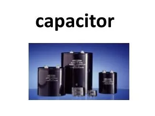
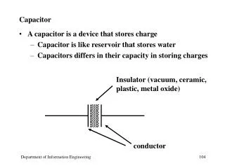
Capacitor. A circuit element that stores electric energy and electric charges. A capacitor always consists of two separated metals, one stores +q, and the other stores –q. A common capacitor is made of two parallel metal plates. Capacitance is defined as: C=q/V (F); Farad=Colomb/volt.

E N D
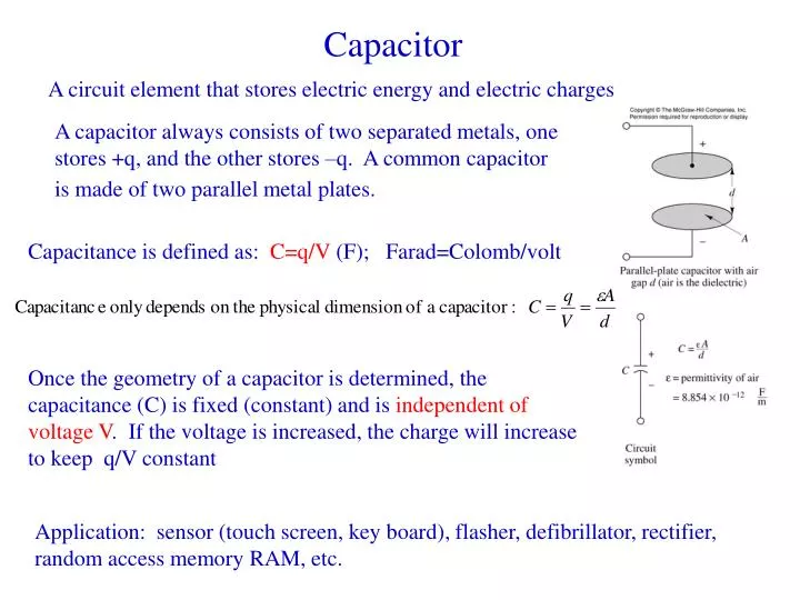
Capacitor A circuit element that stores electric energy and electric charges A capacitor always consists of two separated metals, one stores +q, and the other stores –q. A common capacitor is made of two parallel metal plates. Capacitance is defined as: C=q/V (F); Farad=Colomb/volt Once the geometry of a capacitor is determined, the capacitance (C) is fixed (constant) and is independent of voltage V. If the voltage is increased, the charge will increase to keep q/V constant Application: sensor (touch screen, key board), flasher, defibrillator, rectifier, random access memory RAM, etc.
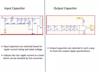
Capacitor: cont. • Because of insulating dielectric materials between the plates, i=0 in DC circuit, i.e. the braches with Cs can be replaced with open circuit. • However, there are charges on the plates, and thus voltage across the capacitor according to q=Cv. • i-v relationship: i = dq/dt = C dv/dt • Solving differential equation needs an initial condition • Energy stored in a capacitor: WC =1/2 CvC(t)2
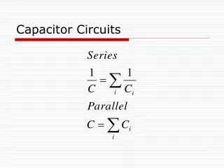
series parallel Capacitors in V=V1+V2+V3 q=q1=q2=q3 V=V1=V2=V3 q=q1+q2+q3
Inductor i-v relationship: vL(t)= LdiL/dt L: inductance, henry (H) Energy stored in inductors WL = ½ LiL2(t) In DC circuit, can be replaced with short circuit
Sinusoidal waves • Why sinusoids: fundamental waves, ex. A square can be constructed using sinusoids with different frequencies (Fourier transform). • x(t)=Acos(wt+f) • f=1/T cycles/s, 1/s, or Hz • w=2pf rad/s • f =2p (Dt / T) rad =360 (Dt / T) deg.
Average and RMS quantities in AC Circuit It is convenient to use root-mean-square or rms quantities to indicate relative strength of ac signals rather than the magnitude of the ac signal.
b a Complex number review Euler’s indentity
Phasor How can an ac quantity be represented by a complex number? Acos(wt+q)=Re(Aej(wt+q))=Re(Aejwtejq ) Since Re and ejwtalways exist, for simplicity Acos(wt+q) Aejq=Aq Phasor representation Any sinusoidal signal may be mathematically represented in one of two ways: a time-domain form v(t) = Acos(wt+q) and a frequency-domain (or phasor) form V(jw) = Aejq=Aq In text book, bold uppercase quantity indicate phasor voltage or currents Note the specific frequency w of the sinusoidal signal, since this is not explicit apparent in the phasor expression
AC i-V relationship for R, L, and C Source vS(t) =Asinwt Resistive Load vR and iR are in phase Phasor representation: vS(t) =Asinwt = Acos(wt-90°)= A -90°=VS(jw) IS(jw) =(A / R)-90° Impendence: complex number of resistance Z=VS(jw)/ IS(jw)=R Generalized Ohm’s law VS(jw) = Z IS(jw) Everything we learnt before applies for phasors with generalized ohm’s law
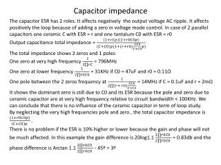
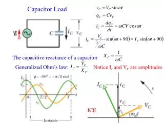
Capacitor Load ICE VC(jw)= A -90° Notice the impedance of a capacitance decreases with increasing frequency
Inductive Load ELI Phasor: VL(jw)=A -90° IL(jw)=(A/wL) -180° ZL=jwL Opposite to ZC, ZL increases with frequency
AC circuit analysis • Effective impedance: example • Procedure to solve a problem • Identify the sinusoidal and note the excitation frequency. • Covert the source(s) to phasor form • Represent each circuit element by its impedance • Solve the resulting phasor circuit using previous learnt analysis tools • Convert the (phasor form) answer to its time domain equivalent.
Ex. 4.21 P188 R1=100 W, R2=75 W, C= 1mF, L=0.5 H, vS(t)=15cos(1500t) V. Determine i1(t) and i2(t). Step 1: vS(t)=15cos(1500t), w=1500 rad/s. Step 2: VS(jw)=15 0 Step 3: ZR1=R1, ZR2=R2, ZC=1/jwC, ZL=jwL Step 4: mesh equation