Download
1 / 55
550 likes | 750 Views
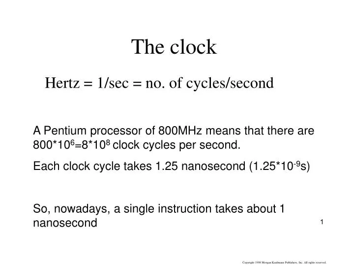
The clock. A Pentium processor of 800MHz means that there are 800*10 6 =8*10 8 clock cycles per second. Each clock cycle takes 1.25 nanosecond (1.25*10 -9 s) So, nowadays, a single instruction takes about 1 nanosecond. Hertz = 1/sec = no. of cycles/second. The idea behind Pipelining.

E N D
The clock A Pentium processor of 800MHz means that there are 800*106=8*108 clock cycles per second. Each clock cycle takes 1.25 nanosecond (1.25*10-9s) So, nowadays, a single instruction takes about 1 nanosecond Hertz = 1/sec = no. of cycles/second
The idea behind Pipelining Never waste time !!!
l w I n s t r u c t i o n f e t c h 0 M u x 1 I F / I D I D / E X E X / M E M M E M / W B A d d A d d 4 A d d r e s u l t S h i f t l e f t 2 n o R e a d i t c r e g i s t e r 1 A d d r e s s P C u R e a d r t d a t a 1 s R e a d n I Z e r o r e g i s t e r 2 I n s t r u c t i o n R e g i s t e r s A L U R e a d A L U m e m o r y 0 R e a d W r i t e A d a t a 2 r e s u l t 1 d a t a r e g i s t e r M M u u W r i t e x x d a t a 1 0 W r i t e d a t a 1 6 3 2 S i g n e x t e n d
l w 0 I n s t r u c t i o n d e c o d e M u x 1 I F / I D I D / E X E X / M E M M E M / W B A d d A d d 4 A d d r e s u l t S h i f t l e f t 2 n o R e a d i t c r e g i s t e r 1 A d d r e s s P C u R e a d r t s d a t a 1 R e a d n I Z e r o r e g i s t e r 2 I n s t r u c t i o n R e g i s t e r s A L U R e a d A L U m e m o r y 0 R e a d W r i t e A d d r e s s d a t a 2 r e s u l t 1 d a t a r e g i s t e r M M u D a t a u W r i t e x m e m o r y x d a t a 1 0 W r i t e d a t a 3 2 1 6 S i g n e x t e n d
l w 0 M e m o r y M u x 1 I F / I D I D / E X E X / M E M M E M / W B A d d A d d 4 A d d r e s u l t S h i f t l e f t 2 n o R e a d i t c r e g i s t e r 1 A d d r e s s P C u R e a d r t d a t a 1 s R e a d n I Z e r o r e g i s t e r 2 I n s t r u c t i o n R e g i s t e r s A L U R e a d A L U m e m o r y 0 R e a d W r i t e A d d r e s s d a t a 2 r e s u l t 1 d a t a r e g i s t e r M D a t a M u u m e m o r y W r i t e x x d a t a 1 0 W r i t e d a t a 1 6 3 2 S i g n e x t e n d
l w 0 M u W r i t e b a c k x 1 I F / I D I D / E X E X / M E M M E M / W B A d d A d d 4 A d d r e s u l t S h i f t l e f t 2 n o R e a d i t c r e g i s t e r 1 A d d r e s s P C u R e a d r t d a t a 1 s R e a d n I Z e r o r e g i s t e r 2 I n s t r u c t i o n R e g i s t e r s A L U R e a d A L U m e m o r y 0 R e a d W r i t e A d d r e s s d a t a 2 r e s u l t 1 d a t a r e g i s t e r M D a t a M u m e m o r y u W r i t e x x d a t a 1 0 W r i t e d a t a 1 6 3 2 S i g n e x t e n d
A correction !!! Keep the right Rd all the way!
A demonstration of a sequence of instructions: Lw $10,20($1) Sub $11,$2,$3 And $12,$4,$5 Or $13,$6,$7 Add $14,$8,$9
An example for data hazards: sub $2, $1, $3 and $12, $2, $5 or $13, $6, $2 add $14, $2, $2 sw $15, 100($2)
An example for data hazards: sub $2, $1, $3 and $12, $2, $5 or $13, $6, $2 add $14, $2, $2 sw $15, 100($2) An example for data hazards:Register $2 is updated only at the WB phase, i.e., the 5th clock cycle (actually at the end of the 5th clock cycle). However, we try to use it at the 3rd clock cycle when we read $2 at the decode phase of the and instruction
Solving data hazards by adding nops sub $2, $1, $3 nop nop nop and $12, $2, $5 or $13, $6, $2 add $14, $2, $2 sw $15, 100($2)
T i m e ( i n c l o c k c y c l e s ) C C 1 C C 2 C C 3 C C 4 C C 5 C C 6 C C 7 C C 8 C C 9 C C 10 C C 11 C C 12 V a l u e o f r e g i s t e r $ 2 : 1 0 1 0 1 0 1 0 1 0 / – 2 0 – 2 0 – 2 0 – 2 0 – 2 0 – 2 0 – 2 0 – 2 0 s u b $ 2 , $ 1 , $ R R R g g g e e e I I I M M M R R R e e e g g g D D D M M M P r o g r a m e x e c u t i o n o r d e r ( i n i n s t r u c t i o n s ) R e g I M R e g D M I M D M R e g R e g I M D M R e g R e g I M D M R e g R e g I M D M R e g R e g Solving data hazards by adding nops 3 nop nop nop 5 a n d $ 1 2 , $ 2 , $ o r $ 1 3 , $ 6 , $ 2 2 a d d $ 1 4 , $ 2 , $ ) s w $ 1 5 , 1 0 0 ( $ 2
The internal structure of the Register File Rd reg 1 (= Rs) 32 5 32 32 32 32 Read data 1 write data 32 32 32 Rd reg 2 (= Rt) 5 32 32 32 Read data 2 32 32 Wr reg (= Rd) 5 E RegWrite We read 2 different registers from the 2 outputs simultaneously We write to one of the registers (in the next rising edge of the CK).
T i m e ( i n c l o c k c y c l e s ) C C 1 C C 2 C C 3 C C 4 C C 5 C C 6 C C 7 C C 8 C C 9 C C 10 C C 11 C C 12 V a l u e o f r e g i s t e r $ 2 : 1 0 1 0 1 0 1 0 1 0 / – 2 0 – 2 0 – 2 0 – 2 0 – 2 0 – 2 0 – 2 0 – 2 0 s u b $ 2 , $ 1 , $ R R g g e e I I M M R R e e g g D D M M P r o g r a m e x e c u t i o n o r d e r ( i n i n s t r u c t i o n s ) R e g I M R e g D M I M D M R e g R e g I M D M R e g R e g I M D M R e g R e g I M D M R e R e g We could earn 1 ck cycle if GPR is “transparent” 3 nop nop 5 a n d $ 1 2 , $ 2 , $ o r $ 1 3 , $ 6 , $ 2 We could earn 1 ck cycle if GPR is “transparent”, i.e, we could see the write data to the GPR at the GPR outputs (if the write address equals the read address), i.e., during Ck #5. 2 a d d $ 1 4 , $ 2 , $ g ) s w $ 1 5 , 1 0 0 ( $ 2
The internal structure of the modified Register File. We ‘bypass” the input data (the write data) to the read data1 output whenever Rs=Rd/Rt (i.e., whenever read reg1=write reg but not zero). We “bypass” the input data (the write data) to the read data2 output whenever Rt=Rd/Rt (i.e., whenever read reg2=write reg, but not zero). Wr reg 5 Rd reg 1 (= Rs) 5 write data 32 32 Read data 1 32 0 32 32 32 32 32 write data 32 32 Wr reg 32 5 Rd reg 2 (= Rt) write data 5 32 Read data 2 32 0 32 32 32 32 32 32 Wr reg (= Rd) 5 E RegWrite We read 2 different registers from the 2 outputs simultaneously We write to one of the registers (in the next rising edge of the CK).
After doing that change we only need 2 nops sub $2, $1, $3 nop nop and $12, $2, $5 or $13, $6, $2 add $14, $2, $2 sw $15, 100($2) After the change the WB of an early instruction can happen at the same time with the read reg (decode) phase of a newer instruction (3 with two other instructions in between). In case we have a data hazard, we need to add only two nop instructions.Unfortunately, this happens too often. We need a better solution!
Forwarding (done at the execute phase) If ID/EX.Rs=EX/MEM.Rd, i.e., the Rd of the previous instruction equals the Rs of the current instruction (which is in the “decode” phase), then we use the “ALUout” of the previous instruction instead of the output of the GPR. If ID/EX.Rs=MEM/WB.Rd, i.e., the Rd of the previous instruction equals the Rs of the current instruction (which is in the “decode” phase), then we use the “ALUout” of the previous instruction instead of the output of the GPR. [ similarly, compare also ID/EX.Rt to MEM/WB.Rd ] Similarly, compare also ID/EX.Rt to EX/MEM.Rd and to MEM/WB.Rd
Data hazard from previous instruction: ALU Src A: If (ID/EX.Rs = = EX/MEM.Rd) use the “ALUOut” instead of Rs I.e., if Rs of the current executing instruction = = Rd of the previous instruction The actual equations are: if ((EX/MEM.RegWrite = = ‘1”)&& (EX/MEM.Rd <> 0)&& (ID/EX.Rs = = EX/MEM.Rd)) => ForwardA=“1,0” ALU Src B: If (ID/EX.Rt = = EX/MEM.Rd) use the “ALUOut” instead of Rt I.e., if Rt of the current executing instruction = = Rd of the previous instruction The actual equations are: if ((EX/MEM.RegWrite = = ‘1”)&& (EX/MEM.Rd <> 0)&& (ID/EX.Rt = = EX/MEM.Rd)) => ForwardB=“1,0”
ALU Src A: If (ID/EX.Rs = = MEM/WB.Rd) use the GPR “write data” instead of Rs I.e., if Rs of the current executing instruction = = Rd of 2 instructions ago The actual equations are: if ((MEM/WB.RegWrite = = ‘1”)&& (MEM/WB.Rd <> 0)&& (ID/EX.Rs = = MEM/WB.Rd)) => ForwardA=“0,1” Data hazard from 2 instructions back: ALU Src B: If (ID/EX.Rt = = MEM/WB.Rd) use the GPR “write data” instead of Rt I.e., if Rt of the current executing instruction = = Rd of 2 instructions ago The actual equations are: if ((MEM/WB.RegWrite = = ‘1”)&& (MEM/WB.Rd <> 0)&& (ID/EX.Rt = = MEM/WB.Rd)) => ForwardB=“0,1” Double hazard: If there is a hazard from previous inst and the instruction before that?We should chhose the data from the previous instruction, it is up to date (“newer”)!
An example for forwarding Sub $2, $1, $3 And $4, $2, $5 needs forwarding from the previous instruction Or $4, $4, $2 needs forwarding from two instructions back Add $9, $4, $2 needs forwarding from 3 instructions back (thru the “transparent” GPR) Here we discuss the $2 register only (The first two cases are handled in the execute phase, the last one, in the decode phase).
An example for forwarding Sub $2, $1, $3 And $4, $2, $5 Or $4, $4, $2 needs forwarding from the previous instruction Add $9, $4, $2 needs forwarding from the previous instruction Here we discuss the $4 register and there are two case(the 2nd one in purple)
Since Rs=2 and Rd of previous inst. was 2, we use ALUout instead of Rs
In red we see forwarding from two instructions back (Mem->Exec.), in purple, from previous instruction (WB->Exec.),in blue, from 3 instructions back (WB->Decode).
The solution does not work for lw (in lw we do not have the data in the pipe!, it comes from the data memory!) If the previous instruction was lw to a register and we try to use the register in the current instruction, we have a problem, since we cannot go back in time! One solution is to avoid such cases by adding a nop (by the Assembler) whenever Rt of the lw is equal to Rs or Rt of the following instruction.
Another h/w solution is to add Bubbles,i.e., add nop by hardware “nop” We need to hold IF/ID for one ck cycle and insert a “nop: into ID/EX. This is equal to adding a nop instruction by the Assembler.
identifies lw Rs, Rt of current inst. Hazard detection unit Rt from prev. inst. We need to hold the IF/ID and PC for one ck cycle and insert a “nop: into ID/EX. This is equal to adding a nop instruction by the Assembler. If (ID/EX.MemRd)&& ( (ID/EX.Rt= =IF/ID.Rs) || (ID/EX.Rt= =IF/ID.Rs) ) we must “stall” the pipeline! This means that prev. inst was lw and it was to the current Rs or Rt. (of course if one of them is not used, don’t stall) Holding means”freeze” the IF/ID and the PC for 1 clock cycle Hold the IF/ID by not giving a IF/IDWrire signal and do not increment the PC (which already points at the nex instruction) by not giving the PCWrite signal. Inserting a nop is by clearing all control signals.
An example for lw hazard detection lw $2, 20($1) And $4, $2, $5 Or $4, $4, $2 Add $9, $4, $2
The lw instruction is in the WB phase. $2 is “being written”. We can use $2 in the Execute phase of the and instruction, with the help of forwarding.
Just to remind us how branch is handled we show again the Datapath with Control
Branch Hazards Here we calc.Rs-Rt These 3 instructions should be “killed” before they do harm, I.e., change any register. Here we decide to branch (switching the address to the PC and issuing PCWrite Cond) In cc5 we already use the new PC calculated by the branch. (PC=72)
The situation was better if we some how “moved” the branch address calculation one ck earlier. This is easy to dosince sign extension and shift are only wires. We just need to move the branch address ALU 1 register to the left. Rverything happens 1 ck earlier and so we’ll have to “kill” only two instructions.Next, we’ll add a fast comparator which will compare Rs and Rt at the same ck cycle of the “decode” phase. (Instead of using the ALU to calc. Rs-Rt, we’ll built a simple and fast xor circuit). This means extra h/w but now we earned one more ck cycle. So, we have to kill only a single instruction.Killing an instruction also called “flushing” the pipeline, is easily done by clraing the IF/ID register of the instruction following the branch (if the branch is successful)