Download
1 / 40
400 likes | 406 Views
This update provides an overview of the mission objectives, flight objectives, instrument status, and summary for the High-Altitude Direct-Detection Doppler LIDAR Mission. The mission aims to demonstrate the capabilities of Doppler LIDAR technologies from a high-altitude platform and validate instrument performance models and atmospheric models.

E N D
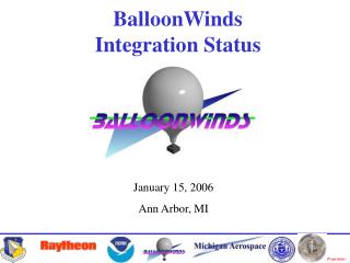
BalloonWinds Update Author: Ivan Dors – UNH (Ivan.Dors@UNH.edu) Presented By: Michael Dehring -- MAC 28 June 2006
Overview • Big Picture • Mission Objectives • Flight Objectives • Instrument Status • Summary
Big Picture • Demonstrate direct-detection Doppler LIDAR technologies from 30 km above the Earth
Mission Timeline 5 4 • Liftoff - System Startup • Emit Laser and Signal Fiber Alignment • Flight Altitude Checkout • Eight-Hour Data Collection • Extended Data Collection (resources/weather) • Descent 6 1 2 3
Mission Objectives • Demonstrate direct-detection Doppler LIDAR fringe imaging from a high-altitude downward-looking platform • Validate instrument performance models and atmospheric models @ 355 nm • Assess the scalability of key subsystems to a space-borne Doppler LIDAR instrument • Scale performance to a space-borne LIDAR
Mission ObjectivesModel Validation Wind Uncertainty Model Atmosphere Model Laser-Telescope Model Optics-Camera Model
Flight I Objectives Demonstrate the electrical, thermal, mechanical, and optical performance of the integrated instrument for nighttime flight conditions
Flight II Objectives Demonstrate the ability to operate during the daytime given the additional thermal load and the increased optical background
Flight III Objectives Demonstrate Photometric measurement Spectral measurement Velocity measurement Validate Space instrument model Subsystem scalability
Flight I &II Priorities • Engineering • Optical Performance • Photometric Return • Aerosol-molecular ratio • Velocity
System Status • Instrument is integrated to the gondola • Post-integration tests are being performed • Thermal system • Pressure chambers & mechanical system • Power distribution system • Instrument health monitoring • Control system • Instrument & optical system • Data & communication system
Thermal System • Additional heating pads added for ascent • Excess heat dissipated with ~0.2 m3 ice • Heat transferred with Propylene Glycol/DI Water 50% • Temperature control loops operational • System allows for 12+ hours of operation
Telemetry Data • 65 Temperature Sensors • 10 Pressure Sensors • 3 Fluid Flow Sensors • 46 Current Monitors • 2 Voltage Monitors • 11 Fan Speed Monitors • 2 GPS Sensors • 2 Attitude Sensors • 2 Decompression Sensors
Laser Chamber Status • Power steady at 3W (exiting chamber) • Seeding stable • Beam profile unchanged • Beam steerer, shutters, attenuator, and reference injection are operational • Heater pads added for thermal stability on ascent
Laser-Telescope Status • Alignment routines are operational and are being refined • Beam finding • Outer-fiber signal characterization • Alignment maintaining
Laser-Telescope Status • Fixture used to test laser-telescope misalignments • System aligned in up- and down-looking positions • Misalignments <15% of steerer range • Fixture was the main cause
Interferometer Status • Finesse • A-Channel: 5.6 • M-Channel: 6.3 • Recycling • A-Channel: 2.1 • M-Channel: 1.9 • Reference row • A-Channel: 10 • M-Channel: 12
System MeasurementComparison Pre-Ship Post-Ship
Scheduled Tests • Mission Simulated Operations (July: UNH) • Dress rehearsal • Review complete flight timeline • Formally assign roles • Test operating procedures in real time • Test problem recovery procedures
Scheduled Tests • Lift Test (July: UNH) • Use a crane to lift the gondola • Test gondola structural integrity • Test opto-mechanics & alignment • Laser-telescope system • Interferometer • Make measurements with swing and rotation
Scheduled Tests • Environmental Test (Aug: Kirtland AFB) • Flight profile in real time • No solar loading or radiation losses • Effects have been calculated • Radiation blankets will limit effects • Make repairs and repeat if necessary
Summary • System is integrated to gondola • Testing phase has begun • Flights 1 & 2 will are scheduled for this fall • Primary objectives for first two flights are engineering/system oriented