Download
1 / 26
361 likes | 902 Views
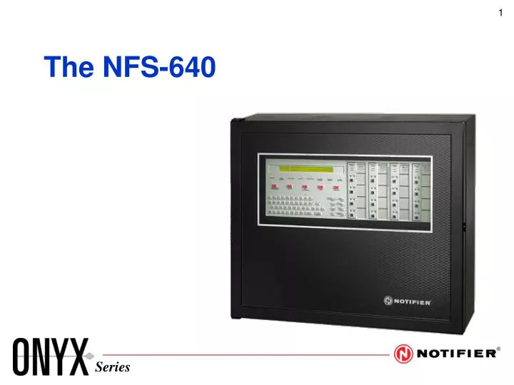
The NFS-640. XPIQ. Single Board Integrated Design. CPU-640 Board. J7 Auxiliary Power Harness for AMG, FFT, NCA, UZC. AC Hot TB2 AC Neutral TB2 Earth Ground TB2 Battery Negative (-) TB1 Battery Positive (+) TB1 12-55 AH. Power Connections TB1, TB2, J7.

E N D
J7 Auxiliary Power Harness for AMG, FFT, NCA, UZC AC Hot TB2 AC Neutral TB2 Earth Ground TB2 Battery Negative (-) TB1 Battery Positive (+) TB1 12-55 AH Power ConnectionsTB1, TB2, J7
NAC/Releasing CircuitsTB3, TB4, TB5, TB6 Degrade Mode for NAC Up = Enable Down = Disable SW6 = NAC1 SW7 = NAC2 SW8 = NAC3 SW9 = NAC4 TB3 NAC 4 TB4 NAC 3 TB5 NAC 2 TB6 NAC 1 SW8 SW6 SW7 SW9 REL 2.2K
24VDC Auxiliary OutputsTB7, J8 24 VDC Non-resettable 24 VDC Resettable Maximum current not to exceed 1.25A per circuit System Reset removes resettable power for 15 seconds. J8 1.25A @ 24 VDC Auxiliary output to UZC-256 Bell Input
NO NC C NO NC C NO NC C NO NC C TB8 TB9 TB10 TB11 RelaysTB8, TB9, TB10, TB11 Alarm Trouble Supervisory Security SW5 converts Security to Alarm SW1 converts Supervisory to Alarm
* + 1 2 3 4 5 6 7 8 9 0 Q W E R T Y U I O P # - A S D F G H J K L Esc & ( Enter / ) Lower Case Z X C V B N M SPACE KDM-2 Display
AC POWER FIRE ALARM PRE-ALARM SECURITY SUPERVISORY SYSTEM TROUBLE SIGNAL SILENCE POINT DISABLED ACKNOWLEDGE SCROLL DISPLAY SIGNAL SILENCE DRILL HOLD 2 SECONDS SYSTEM RESET LAMP TEST NEXT SELECTION DETECTOR PREVIOUS SELECTION * + 1 2 3 4 5 6 7 8 9 0 MODULE RECALL LAST ENTRY Q W E R T Y U I O P # - OUTPUT A S D F G H J K L Esc & ( BATTERY LEVELS INCREMENT NUMBER Enter / ) Lower Case Z X C V B N M SPACE KDM-2 Display
1 2 3 4 5 6 7 8 9 0 * + Esc # - Q W E R T Y U I O P A S D F G H J K L & ( Lower Case Z X C V B N M Space Enter / ) NCA Display
Displayless Node OperationAuxiliary Control Panel AC Power Alarm Pre-Alarm Security Acknowledge Silence Reset Supervisory Trouble Signal Silence Point Disabled
SLC ConnectorTB16 - NFS-640; TB1 - LEM-320 Typical Style 6.0/7.0 Typical Style 4.0 Channel B Channel A Channel A Return Channel B Output
Terminal Annunciators ACS Annunciators 24 VDC Non-Resettable Regulated TB12 TB13 EIA-485 ConnectorsTB12, TB13
NOTIFIER REMOTE LCD ANNUNCIATOR ALL SYSTEMS NORMAL 12:10P 01/11/01 REMOTE LCD ANNUNCIATOR ALL SYSTEMS NORMAL 03:17P 01/11/01 Hold for Status Ack/ Step Status Contrast Contrast Adjust Signal Silence Lamp Test Ack/Step Lamp Test System Reset Silence Reset Terminal Annunciators LCD-80 LCD-80TM
ACK Trouble On Line ACK Trouble On Line A1P1 A1P2 A1P3 A1P4 A01P01 A01P09 A01P01 A01P02 A01P10 A01P03 A01P11 A01P04 A01P12 A01P05 A01P13 A01P06 A01P14 A01P07 A01P15 A01P08 A01P16 A01P32 ACM Series ACM(AEM)-24AT ACM(AEM)-32A ACM(AEM)-16AT
Repeaters RPT-485W RPT-485WF
All Auto Manual Acknowledge Switch Group 1 Switch Group 2 Switch Group 3 Switch Group 4 Switch Group 5 Switch Group 6 Switch Group 7 Switch Group 8 1 2 3 4 5 6 7 8 0 0 9 9 1 1 8 8 2 2 3 7 3 7 6 6 4 4 5 5 Special Annunciators
AUDIO MESSAGE GENERATOR AUDIO LEVEL ALL CALL ON LINE TROUBLE ALL CALL LOCAL SPEAKER VOLUME Audio Message Generator
EMERGENCY MICROPHONE POWER MICROPHONE TROUBLE Audio Components
R100 R107 Audio Amplifiers AA-100/AA-120 AA-30
AMG 8 7 6 5 4 3 2 1 P4 P3 P2 P1 PAGE MODE ON LINE FIRE FIGHTERS TELEPHONE PAGE PHONE TROUBLE LINE TROUBLE Audio Components
EIA-232 Devices PRN Series Printer CRT2 Terminal Keltron VS4095 Printer
Power Supplies APS-6R CHG-120