Download
1 / 1
10 likes | 153 Views
Tightness Sensor. Capacitive structure that serves to monitor connector tightness As connector fits in, the chamfered surface deflects toward the capacitive ring on the outside of the disk

E N D
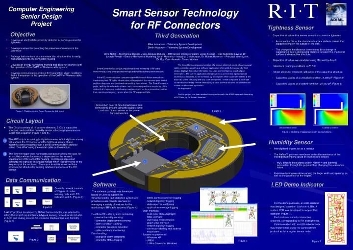
Tightness Sensor • Capacitive structure that serves to monitor connector tightness • As connector fits in, the chamfered surface deflects toward the capacitive ring on the outside of the disk • The change in the distance is monitored by a change in capacitance due to decreasing distance between the chamfered surface and capacitive structure. • Capacitive structure was modeled using Maxwell by Ansoft • Maximum Loading conditions is 25 ft-lb • Model allows for threshold calibration of the capacitive structure • Capacitive values at a unloaded condition, 9.286 pF (Figure 6) • Capacitive values at a loaded condition, 26.033 pF(Figure 6) Circuit Layout • The Circuit consists of 11 passive elements, 2 ICs, a capacitive structure, and a relative humidity sensor, all occupying a space no larger than a quarter (Figure 1 and 5). • The ADC chip is an analog to digital converter which digitizes analog values from the RH sensor and the tightness sensor. It also transmits sensor readings over a serial communication protocol called “One-Wire” using the coaxial cable as the medium. • The Schmitt trigger input nand gate package provides the basis for an oscillator whose frequency is dependent on the sensed capacitance of the connector housing. A charge pump circuit converts this signal to an analog voltage which is proportional to the frequency of the oscillator. The output from this same oscillator provides the stimulus for sensing relative impedance of the RH sensor. Figure 1. Relative size of Smart Connector disk insert Unloaded Condition Loaded Condition Humidity Sensor • Interdigitized fingers act as a resistor • The Nafion™ polymer membrane varies the resistance of the interdigitized fingers based on its moisture content. • H2O binds to the sulfonic acid in Nafion™ and allowing permeation through the polymer thus changing the resistance value. • Extensive testing was done varying the finger width and spacing, as well as the geometry of the fingers. 2 1 1 2 Computer Engineering Senior Design Project Smart Sensor Technology for RF Connectors Objective Third Generation • Develop an electrostatic proximity detector for sensing connector tightness • Develop a sensor for detecting the presence of moisture in the connector • Package both sensors on a substrate disc structure that is easily manufactured into the connector housing • Develop an energy harvesting method that does not interfere with the operation of the CATV or Wireless cable system. • Develop communication protocol for transmitting alarm conditions that is transparent to the operation of the CATV or Wireless cable system Mike Iannacone - Telemetry System Development Dmitri Yudanov – Telemetry System Development Chris Natoli – Mechanical Design, Jean-Jacques DeLisle – RH Sensor Characterization, Jesse Steiner – Disc Substrate Layout, Dr. Joseph Revelli – Electro-Mechanical Modeling, Noah Montena – Industrial Collaborator, Dr. Robert Bowman – Principal Investigator, Dr. Roy Czernikowski - Project Advisor The SmartConnector project consists of a sensor which sits inside of each coaxial cable connector, as well as a software application which polls the sensors for their status, displays this status information to a user, and maintains a log of all past information. The current application allows numerous connectors, spread across several coaxial cables, to be monitored by a computer which could be installed at the base of a tower site along with any other equipment. These computers at each site could be monitored by remote desktop log-in from a central location, or an technician on-site could use the application for diagnostics. For this project, our team worked in conjunction with the ADIML research laboratory at RIT, lead by Dr. Robert Bowman. SmartConnector is a unique project that allows monitoring of RF cable interconnects, using emerging technology and multidisciplinary team research. In the US, communication companies spend billions of dollars annually on maintaining their RF cable infrastructure. A huge part of this expense goes toward problem diagnosis, and the downtime resulting from failures. The SmartConnector project will significantly reduce these costs, by allowing real-time monitoring of the status of all connectors, and allowing maintenance to be done preventively, rather than requiring emergency repairs when this RF equipment fails. Connection point of data transmission from connector to system using the cable’s center conductor. It also serves as the power transmission line Figure 5 Figure 6. Modeling of capacitance with load conditions. ™ Data Communication Software LED Demo Indicator Scalable network consists of 2 types of nodes: sensing node and LED indicator switch. (Figure 2) The software package was developed based on Java to support the SmartConnector fault detection system and provides a user-friendly interface for managing a variety of features for the monitoring of RF-cable systems (Figure 4): Real time RF-cable system monitoring: - internal humidity sensing - connector displacement sensing - alarm condition tracking - connector presence detection - cable continuity monitoring Data handling: - backup of alarm conditions - connector status logging - latest alarm occurrence logging - network topology logging - data export in text format - application message logging User Interface: - multi-color status highlight - table interface - chart data representation - graph view interface - network topology logging - connector labeling and address visualization System requirements: - Windows XP - JRE 6 - 1-Wire Drivers for Windows For the demo purposes, an LED oscillator was designed based on dual-color LEDs. A custom PCB was developed to support this oscillator (Figure 7). Each indicator circuit contains two channels, corresponding to RH and tightness. Communication with an LED network node was implemented using the same network protocol as for a regular sensor node. Figure 2 1-Wiretm protocol developed by Dallas Semiconductor was selected to satisfy the project requirements. A typical sensing network node includes an ADC and analog sensors for connector displacement and humidity. (Figure 3) Figure 3 Figure 4 Figure 7