Download
1 / 20
200 likes | 203 Views
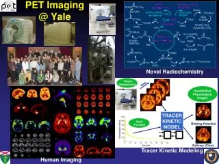
Optical links application in surgical probes and PET imaging scenarios. Georgios Konstantinou Rigoberto Chil Juan José Vaquero. Two medical scenarios. Scenario1:Intraoperative Gamma camera Portable handheld application Miniaturization of electronics Movement free back-end communication.

E N D
Optical links application in surgical probes and PET imaging scenarios Georgios Konstantinou Rigoberto Chil Juan José Vaquero
Two medical scenarios • Scenario1:Intraoperative Gamma camera • Portable handheld application • Miniaturization of electronics • Movement free back-end communication
Two medical scenarios • Scenario 2:MRI compatible PET insert module • Interconnection of several detectors • Minimum electronics inside the MRI chamber • Fixed but bigger back-end communication • Power consumption considerations [M.S. Judenhofer, 2008]
Intraoperative Gamma Camera Applications: - Sentinel lymph node removal - Parathyroid gland surgery - Radioimmunoguided surgery - 18F-fluorodeoxyglucose (FDG) radioguided surgery. [Tsuchimochi 2012], [Wallace 2005]
IntraoperativeGamma Camera Detector electronicsminiaturization Part3 - Anger Logic 164(Xa,Xb,Ya,Yb) Single PCB - Charge distribution - Amplification - Anger logic Part2 Amplification Part1 – Charge distribution network 6416(8x+8y) Previous design Current design
IntraoperativeGamma Camera • Prototype Model • Size considerations • Mobility considerations • Handiness
Intraoperative Gamma Camera • Considerable benefits from real-time in vivo imaging applications • Integration with eg. image-guided surgical systems requires to add real-time space tracking and co-registration with preoperative imaging. • Integration of processing units using powerful modules like the XILINX Zinq is considered
Intraoperative Gamma Camera System Specifications: 1. Maximum data stream of 1.25MB/s (256x256x16bits, 10 frames per second maximum, 4 frames per second in a more realistic case) of images maximum, plus a 10% overload for other information (position, acceleration, temperature, battery status, statistics, etc.). 2. 1 meter radius. 3. The orientation inclined up to 90 degrees 4. Objects or persons blocking the line of view (redundancy is proposed). 5. Drops in signal rate are allowed if recovery doesn’t take more than two or three seconds. 6. Asymmetrical duplex communication is required in order to calibrate and adjust the device. 7. With different proposed configurations of the operating room, using optical wireless communication (OWC) can be a possible solution for the readout of the gamma camera.
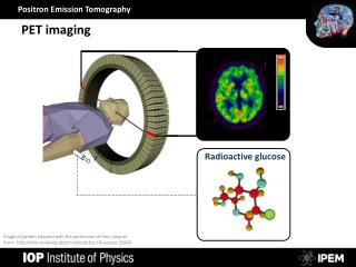
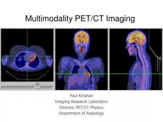
Multimodality PET/MRI imaging system • Why PET/MRI? • Multimodality imaging is a fast-growing field in clinical practice, • Software fusion of images has several drawbacks • On the discussion about PET/MRI vs PET/CT. • MRI does not use ionizing radiation, the radiation dose received during a PET/CT scan depends mainly on the CT • Reducing radiation exposure is especially important when treating children and younger patients • PET/MRI is expected to provide new insights in the study of neuroscience and neurologic disorders, PET may detect especially small lesions with higher sensitivity than MRI [B.J. Pichler, 2010]
Multimodality PET/MRI imaging system Clinical inserts
Multimodality PET/MRI imaging system • Interference from different detector technologies for different types of radiation sharing the same space and Field of View. • Minimum ferromagnetic materials within the MRI chamber (Eddie currents, shadows on the MRI signal, destruction of the PET pcb, especially BGA IPs) • Integration of the insert with the RF coils • SiPM is the only possible technological solution, but the readout?
Multimodality PET/MRI imaging system Possibility of separating the electronics in two stages. SiPM with minimum front end electronics inside the chamber, logical units, pre-proccessing, back-end communication stationed outside. Insert base station
Multimodality PET/MRI imaging system • Where is the bottleneck for optimal OWC application? • Three scenarios: • Scenario I:OWC between internal logic unit and external one (1.5Gbps approx. per ring) • Scenario II:OWC between the output of ADC and an external logic unit (65Gbps approx. per ring) • Scenario III:Analog OWC directly after SiPM (4.8Ghz per ring) • Further implications of the application (shaking gantry, problematic alignment, unknown exact distance) scintilator analog pulse photons SiPM raw Scenario III ADCs Insert base station Scenario II Preprocessing of events Scenario I Further back-end processing (coincidence, reconstruction…) Outline of the PET detector
Multimodality PET/MRI imaging system • Testing and application (Wajahat Ali, SSSA,Pisa): • Work on scenario I where 1.5Gbps OWC system is required. • Characterization of OWC system: Performance and tolerance to misalignment at 2.5 Gb/s with collimators (0.38mm, 0.87mm, 2.1mm, 3.5mm ) and photodiode with focusing lens. Summary of launched power and tolerance to misalignment values Simulated results using bigger diameter ball lens at receiver
Multimodality PET/MRI imaging system • Transmitted power and tolerance values at 0.5m and 1m using all collimators Power penalty vs Displacement
Summary • Collaboration between UC3M and SSSA can prove very beneficial for both • Two distinct and very different medical scenarios have been considered • Work is ongoing especially on the second scenario • With the application of the OWC a potentially disruptive technique can be developed
The end This project has received funding from the European Union’s Seventh Framework Programme for research, technological development and demonstration under grant agreement n° 317446
Multi Ring System • 5x6x24 ADC channels @50MHz • 6x24 acquisition units • 2x24 FPGAs/GE • Wired implementation of communication protocol (UDP) • Data encapsulation with RT CRC computation • Bidirectional comm • Programmable MAC/IP/UDP addresses • Pipelined + buffered architecture for continuous communication • Very high power consumption, need to use heat dissipation systems 5 channels x6 detectors x3 MUX ADC ctrl ADC ctrl FPGA UDP/IP MAC PHY ADC