Download
1 / 29
290 likes | 641 Views
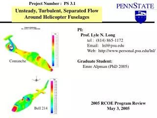
Project Number : PS 7.1 Rotorcraft Fuselage Drag Study using OVERFLOW-D2 on a Linux Cluster PI: Associate Professor EPN Duque tel : 928-523-5842 www.cet.nau.edu/~end2 Northern Arizona University Graduate Assistant/Research Engineer: Nathan Scott

E N D
Project Number : PS 7.1 Rotorcraft Fuselage Drag Study using OVERFLOW-D2 on a Linux Cluster PI: Associate Professor EPN Duque tel : 928-523-5842 www.cet.nau.edu/~end2 Northern Arizona University Graduate Assistant/Research Engineer: Nathan Scott 2004 RCOE Program Review May 4, 2004
Background/ Problem Statement: • Evaluate fuselage force and moment prediction capability of the OVERFLOW2 and OVERFLOW-D • Utilize cost effective computer systems
Technical Barriers orPhysical Mechanisms to Solve : • Appropriate grid generation over specific aircraft • Lift and drag forces over simplified shapes such as prolate spheroid • Grid sensitivity studies required • Unsteady flow capturing on bluff bodies
Task Objectives: Using the OVERFLOW code • Evaluate drag prediction on a prolate spheroid • Evaluate drag prediction on a helicopter fuselage • Evaluate and document effects of grid resolution • Evaluate turbulence models upon predictions. • 1-eqn, 2-eqn, DES • Compare results with Penn State Methods
Approaches: • OVERFLOW2 Code • Grid Generation • Near body grid refinement in boundary layer • Grid adaptation in the field for vortical flow • Turbulence models • Baldwin-Barth • Spalart-Almaras • k-w • Mentor-SST • include Detached Eddy Simulation (DES)
Overview • Explain S-A and SST Detached Eddy simulation • Discuss DES Implementation in OVERFLOW • Circular Cylinder results • 6:1 Prolate Spheroid results
Experimental Data • Virginia Tech Stability Wind Tunnel • Wetzel, Simpson, Ahn • 1.37 m 6:1 Prolate Spheroid • Free stream conditions • α=20º, Re=4.2E6, Ma=0.16 • Coefficient of Pressure (Cp), Skin Friction (Cf)from Wetzel Dissertation • U/u*, y+ from Simpson’s Website
CFD Methodology • Reynolds Averaged Navier-Stokes Equations • OVERFLOW-D code developed at NASA and Army • Uses detailed overset grids • Allows for detailed geometry definition • Captures viscous effects such as unsteady flow separation • OVERFLOW2 used for turbulence model study and Implementation of DES • Scalar penta-diagonal scheme • 1st order difference in time • 2nd or 4th order RHS (OVERFLOW2) • 2nd and 4th order central difference dissipation terms
Detached Eddy Simulation • First Formulated by Spalart as a modification to S-A model in 1997. • Later generalized to any model by Strelets in 2001. • First step was to modify the S-A model
S-A-DES formulation • Change distance to wall in S-A model dw to • Ĩ=min(dw,CDES∆) • ∆ is the maximum of the grid spacing in three dimensions- ∆=max(δX, δY, δZ) • CDES=0.65
k-w-SST-DES Formulation • Change k-transport source term: ρβ*kω=ρk3/2/Ĩ • Ĩ=min(lk-ω,CDES∆) • lk-ω=k1/2/(β*ω) • ∆ is the maximum of the grid spacing in three dimensions- ∆=max(δX, δY, δZ) • CDES=(1-F1) Ck-ε+F1Ck-ω • Ck-ε=0.61, Ck-ω=0.78 • At equilibrium reduces to an algebraic mixing-length Smagorinski type model.
Implementation in OVERFLOW • Determine grid cell edge lengths in J,K,L directions • One sided difference at boundaries • Central difference otherwise • Background Cartesian Grids - DES always enabled
Circular Cylinder Test Case • Re=140,000, Ma=0.2 • Fully Turbulent • S-A, S-A-DES, SST-DES turbulence models • 7.6 million grid points • Near body 181 by 60 by 99 • Background 426 by 61 by 252 • Off Body grid resolution 0.05 the diameter • H type block grid extends 10 diameters • 2 total grids • Methods • 4th central difference in space • 1st order Beam-Warming in time • Inviscid wall Boundary Conditions
Other DES work with Cylinder • Travin, A, Shur, M, Strelets, M, Spalart, P • Re = 50,000 and 140,000 • Laminar Separation • Laminar Separation • LES in Background • Turbulent Separation • Run Fully Turbulent • Compares to higher Re
Iso-surface visualization comparison Circular Cylinder OVERFLOW S-A-DES Travin-DES OVERFLOW URANS (Not Unsteady Yet) OVERFLOW k-w-SST-DES
Conclusions from Circular Cylinder • S-A DES in OVERFLOW looks promising • More fine scale resolution • Cross Flow on “2-D” cases • Comparable comparisons to Experimental Data • k-w-SST DES in OVERFLOW also looks promising • SST has been shown to approximate separation better so more desirable in shear layer • More verification needs to be done
6:1 Prolate Spheroid Test Case • Re=4,200,000, Ma=0.16 • Trip to Turbulence at x/L=0.2 • S-A, S-A-DES, SST-DES turbulence models • 7 million grid points • Near body 361 by 310 by 45 • First off body Grid spacing 0.08 the length • Remaining off body grids reduce in resolution by half • Off body grids extent to 10 times the length • 61 Total grids • Grid shown to be convergent in Previous Study • Methods • 4th central difference in space • 1st order Beam-Warming in time
Other DES work with 6:1 Prolate Spheroid • Rhee, S. H. and Hino,T. • Re = 4,200,000 Ma=0,16 • Run Steady and Unsteady • Showed under prediction of Lift
Surface Skin Friction and vorticty contour comparison for 6:1 Spheroid S-A DES S-A SST SST DES
Comparison Of Lift and Pitching Moment for 6:1 Spheroid • All of the models fall with error for Pitching Moment • All of the models under predict lift
6:1 Spheroid Conclusions • DES shown to work with overset grids • DES did not improve integrated forces • Skin friction remained the same • Surface pressure showed slight improvement • Velocity profiles remained the same close to surface y+<10 • Velocity profiles improved farther away from surface y+>100
Accomplishments • Summer work with Roger Strawn and Mark Potsdam at Ames • Presented at AIAA 43rd Aerospace Sciences Meetings.
Future Work • Grid Refinement Study on 6:1 Prolate spheroid and DES • New research engineer, explore new LES • Apply DES and LES to helicopter fuselage