Download
1 / 33
370 likes | 678 Views
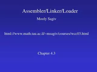
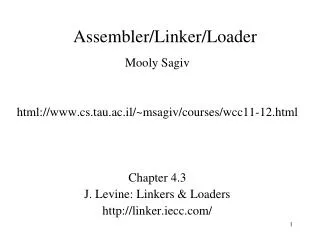
Loader. Role of Loader. Source Program. Translator. Loader. Object Program. Object program ready for execution. Translator – Assembler/Compiler. Memory. Role of Loader and Linker. Memory. Source Program. Assembler. Linker. Object Program. Object program ready for execution.

E N D
Role of Loader Source Program Translator Loader Object Program Object program ready for execution Translator – Assembler/Compiler Memory
Role of Loader and Linker Memory Source Program Assembler Linker Object Program Object program ready for execution Executable Code Loader
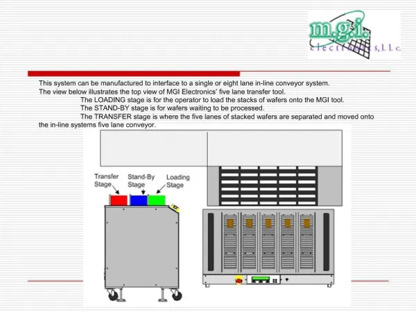
Loader is a system s/w that makes a program ready for execution, by copying the file from secondary memory to main memory for execution. • It is usually part of Operating system. • The main task of the loader is to bring binary executable image into main memory and bind the relocatable addresses into absolute addresses. • The binary image of a program consists of following parts :- • Header – it shows the type of file (executable or library file) • Text – it shows the actual code of the program • List of shared libraries - libraries that have been used in the object file
Design of The absolute loader – • An absolute object file consists of three part- • The start address of the program • The object instructions • The address of the first executable instruction. This is placed in the object file by assembler in response to the END directive. It is either the address specified by the END or, in the absence of such an address is identical to the first address of the program. • The loader reads the first item and loads the rest of object file into successive memory locations.
Algorithm for absolute loader:- Begin Read Header record Verify program name and length Read first text record While record type is not ‘E’ do begin if object code is in character form { convert into internal representation } read next object program record end Jump to the address specified in End Record end
Role of Absolute Loader 1000 Absolute Loader Object Program Object program ready for execution 2000 Memory
Object Program H COPY 001000 00107A T 001000 1E 141033 482039 001036 281030 301015 482061 ... T 00101E 15 0C1036 482061 081044 4C0000 454F46 000003 000000 T 002039 1E 041030 001030 E0205D 30203F D8205D 281030 … T 002057 1C 101036 4C0000 F1 001000 041030 E02079 302064 … T 002073 07 382064 4C0000 05 E 001000
Absolute Loader • Advantage • - Simple and efficient • Disadvantage • - the need for programmer to specify the actual address • - difficult to use subroutine libraries
A Simple Bootstrap Loader • When a computer is first tuned on or restarted, a special type of absolute loader, called bootstrap loader is executed • This bootstrap loads the first program to be run by the computer -- usually an operating system • It is permanently stored in ROM. So it can not be erased.
Example (SIC bootstrap loader) • The bootstrap itself begins at address 0 • It loads the OS at starting address 0x80 • No header record or control information, the object code is consecutive bytes of memory
After load the OS, the control is transferred to the instruction at address 80.
Algorithm of bootstrap loader Begin X=0x80 (the address of the next memory location to be loaded) Loop AGETC (and convert it from the ASCII character code to the value of the hexadecimal digit) save the value in the high-order 4 bits of S AGETC combine the value to form one byte A (A+S) store the value (in A) to the address in register X XX+1 End
GETC reads one character and convert it into hexadecimal digit. For example, the ASCII code for ‘1’ through ‘9’ are converted to the numeric values 1 through 9. and codes for ‘A’ through ‘F’ ( 41 to 46 Hex) are converted to the values 10 through 15. this is accomplished by subtracting 48 ( 30 in Hex) from the character codes of 0-9 and by subtracting 55 (37 in Hex) from the codes of A-F ASCII value of 0~9 : 0x30~39 A~F : 0x41~46
Machine Dependent Loader Features • Relocation • Program Linking
Example of Relocation Line Loc Source statement Object code 5 0000 COPY START 0 10 0000 FIRST STL RETADR 17202D 12 0003 LDB #LENGTH 69202D 13 BASE LENGTH 15 0006 CLOOP +JSUB RDREC 4B101036 20 000A LDA LENGTH 032026 25 000D COMP #0 290000 30 0010 JEQ ENDFIL 332007 35 0013 +JSUB WRREC 4B10105D 40 0017 J CLOOP 3F2FEC 45 001A ENDFIL LDA EOF 032010 50 001D STA BUFFER 0F2016 55 0020 LDA #3 010003 60 0023 STA LENGTH 0F200D 65 0026 +JSUB WRREC 4B10105D 70 002A J @RETADR 3E2003 80 002D EOF BYTE C’EOF’ 454F46 95 0030 RETADR RESW 1 100 0033 LENGTH RESW 1 105 0036 BUFFER RESB 4096
125 1036 RDREC CLEAR X B410 130 132 133 135 140 145 150 155 160 165 170 175 180 185 210 105D WRREC CLEAR X B410 212 215 220 225 230 235 ...(omitted)
Instructions at line no 15,35 & 65 are the only items whose values are affected by relocation. We use modification records for the relocation purpose. Each modification record specifies the starting address and the length of the field whose value to be altered. It then describes the modification to be performed. • Modification record • col 1: M • col 2-7: relocation address • col 8-9: length (halfbyte) • col 10: flag (+/-) • col 11-17: segment name
Modification Record HCOPY 000000 001077 T000000 1D17202D69202D48101036…4B105D3F2FEC032010 T00001D130F20160100030F200D4B10105D3E2003454F46 T001035 1DB410B400B44075101000…33200857C003B850 T0010531D3B2FEA1340004F0000F1..53C003DF2008B850 T00070073B2FEF4F000005 M00000705+COPY M00001405+COPY M00002705+COPY E000000
Begin Get PROGADDR from OS While not end of input do { read next record while record type != ‘E’ do { read next input record while record type = ‘T’ do { move object code from record to location ADDR + specified address } while record type = ‘M’ add PROGADDR at the location PROGADDR + specified address } } end Relocation Loader Algorithm
Modification record scheme is not well suited for use with all machine architectures and if many instructions require relocation then the number of modification record will be very large. • To solve this problem we can use relocation bit method. • If the relocation bit corresponding to a word of object code is set to 1, the program’s starting address is to be added to this word when the program is relocated. • Relocation bit • - 0: no modification is necessary • - 1: modification is needed • Twelve-bit mask is used in each Text record • Since each text record contains < 12 words • Unused words are set to 0
Text record format • Text record • col 1: T • col 2-7: starting address • col 8-9: length (byte) • col 10-12: relocation bits • col 13-72: object code
Relocatable Program for SIC Line Loc Source statement Object code 5 0000 COPY START 0 10 0000 FIRST STL RETADR 140033 15 0003 CLOOP JSUB RDREC 481039 20 0006 LDA LENGTH 000036 25 0009 COMP ZERO 280030 30 000C JEQ ENDFIL 300015 35 000F JSUB WRREC 481061 40 0012 J CLOOP 3C0003 45 0015 ENDFIL LDA EOF 00002A 50 0018 STA BUFFER 0C0039 55 001B LDA THREE 00002D 60 001E STA LENGTH 0C0036 65 0021 JSUB WRREC 481061 70 0024 LDL RETADR 080033 75 0027 RSUB 4C0000 80 002A EOF BYTE C’EOF’ 454F46 85 002D THREE WORD 3 000003 90 0030 ZERO WORD 0 000000 95 0033 RETADR RESW 1 100 0036 LENGTH RESW 1 105 0039 BUFFER RESB 4096
125 1039 RDREC LDX ZERO 040030 130 103C LDA ZERO 000030 135 103F RLOOP TD INPUT E0105D 140 1042 JEQ RLOOP 30103D 145 1045 RD INPUT D8105D 150 1048 COMP ZERO 280030 155 104B JEQ EXIT 301057 160 104E STCH BUFFER,X 548039 165 1051 TIX MAXLEN 2C105E 170 1054 JLT RLOOP 38103F 175 1057 EXIT STX LENGTH 100036 180 105A RSUB 4C0000 185 105D INPUT BYTE X’F1’ F1 190 105E MAXLEN WORD 4096 001000 210 1061 WRREC LDX ZERO 040030 215 1064 WLOOP TD OUTPUT E01079 220 1067 JEQ WLOOP 301064 225 106A LDCH BUFFER,X 508039 230 106D WD OUTPUT DC1079 235 1070 TIX LENGTH 2C0036 240 1073 JLT WLOOP 381064 245 1076 RSUB 4C0000 250 1079 OUTPUT BYTE X’05’ 05 255 END FIRST
Relocation by Bit Mask H COPY 000000 00107A T 000000 1E FFC 140033 481039 000036 280030 300015 481061 ... T 00001E 15 E00 0C0036 481061 080044 4C0000 454F46 000003 … T 001039 1E FFC 040030 000030 E0105D 30103F D8105D … T 001057 1C 800 100036 4C0000 F1 001000 T 001061 19 FE0 040030 E01079 301064 508039 DC1079 2C0036 … E 000000 Here the bit mask FFC (representing the bit string 111111111100) In the first text record specifies that all 10 words of object code are to be modified during relocation. Similarly bit mask E00 represents that the first 3 words are to be modified .
Machine Independent Loader Features • Automatic library search • Loader options
Automatic library search :- This feature allows a programmer to use standard subroutines without explicitly including them in the program to be loaded. So programmer can use any subroutine by just mentioning their names. The subroutines are automatically fetched from the library, linked with the main program and loaded. Loader maintains an External Symbol Table (ESTAB) for these external symbols. The loader searches the library specified for routines that contain the definitions of these symbols, and process the subroutines found by this search. In most cases a special file structure is used for libraries. This structure contains a directory that gives the name of each routine and a pointer to its address within the file.
Loader Options :- • Many loader allow user to specify options that modify the standard processing. Loaders have a special command language that is used to specify the options. • Options:- • INCLUDE • DELETE • CHANGE • LIBRARY
INCLUDE:- this loader option allows the selection of alternative sources of input. For example, the command • INCLUDE program-name (library name) • Might direct the loader to read the designated object program from a library and treat it as the primary loader input. • 2) DELETE:- it allows the user to delete external symbols or entire control sections. For example, the command • DELETE csect-name • might instruct the loader to delete the name control section from the set of programs being loaded. • 3) CHANGE :- it allows the user to change name1 to name 2 in the program. For example • CHAMGE name1 , name 2 • Might cause the external symbol name1 to be changed to name 2 wherever it appears in the object programs
Example of Relocation Line Loc Source statement Object code 5 0000 COPY START 0 10 12 13 15 0006 CLOOP +JSUB RDREC 4B101036 30 35 0013 +JSUB WRREC 4B10105D 40 65 0026 +JSUB WRREC 4B10105D 70 105 125 1036 RDREC CLEAR X B410 130 180 185 210 105D WRREC CLEAR X B410 212 230 235 ...(omitted) INCLUDE READ(ULIB) INCLUDE WRITE(ULIB) DELETE RDREC,WRREC CHANGE RDREC, READ CHANGE WRREC, WRITE
These command would direct the loader to include control sections READ & WRITE from the library ULIB, and to delete the control sections RDREC and WRREC from the load. The first CHANGE command would cause all external references to symbol RDREC to be changed to refer to symbol.