Download
1 / 124
1.26k likes | 1.27k Views
Wind Energy Systems MEMS 5705 Spring 2017 Lecture 11, Feb. 22 Lecture 12, Feb. 27. 1. L11 and L12. Key points of L9 & L10 Momentum Theory and Blade Element Theory 2.1 Momentum theory 2.2 Blade element theory 2.3 Blade shape for ideal rotor without wake rotation

E N D
Wind Energy Systems MEMS 5705 Spring 2017 Lecture 11, Feb. 22 Lecture 12, Feb. 27 1
L11 and L12 • Key points of L9 & L10 • Momentum Theory and Blade Element Theory 2.1 Momentum theory 2.2 Blade element theory 2.3 Blade shape for ideal rotor without wake rotation 2.4 Strip Theory or BEM Theory (A combination of momentum theory and blade element theory) 2
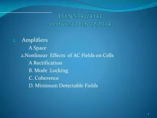
3. Power coefficient Cp including the effects of wake rotation and profile drag 4. Advanced aerodynamics topics (# 3.13, pp. 141-145) 5. Chapter 4: Mechanics and Dynamics 5.1 An overview of basic mechanics 3
Range of validity of momentum theory a = axial induction factor for a ≤ 0.4, momentum theory is considered valid. 2nd Edition (3.12, 3.14), pp. 94-95 For a ≥ 0.4, momentum theory is considered not valid
Airfoil Basics Lift force = L Pitching moment = M Air flow α Drag force = D Chord c/4 Drag and lift forces and pitching moment on stationary airfoil: α : angle of attack ; c: chord (p. 97)
L = Lift force over the reference area c.l Cl = lift coefficient
….(3.43) p. 104 Drag force = D Drag coefficient: Pitching moment = M Pitching moment coefficient: ….(3.44) p. 104
μ = coefficient of viscosity = kinematic viscosity ….(3.41) p. 103 (* we take chord length c as reference length)
Momentum Theory with Wake Rotation (#3.3, pp. 96-101) Stream tube model of flow behind rotating wind blade. Picture of stream tube with wake rotation.
An important statement in the text (p. 97) Momentum Theory with Wake Rotation “Note that when wake rotation is included in the analysis, the induced velocity at the rotor consists of not only the axial component, Ua, But also a component in the rotor plane rΩa'.” (a' = angular induction factor)
a'r Ω Wind Direction aU For future reference: U(1-a) U Relative Velocity rΩ Plane of Rotation Flow velocity diagram at an annulus in a HAWT rotor disk
2nd Edtion (3.26-27) p. 98 2nd Edition (2.76) p. 63 2nd Edition (3.25) p. 98 We will further verify this geometrical derivation analytically.
2. Momentum Theory and Blade Element Theory (# 3.6, pp. 117-121) 15
2.1 Momentum Theory (L9 + L10) 2nd Edition (3.58-59) p. 118 dL = 4b[1-b*cos(φ)](1/2)ρUΩr2(2πrdr) = 4b[1-a]ρUr3(πΩdr) . . . . . . . . . . Peters
Blade Geometry for HAWT Aerodynamic Analysis A typical blade element of length dr and width c Plane of Rotation Chord line Ф θ = θp dFT dL = dFL α Ur Ω r ( 1+ a') θ (class) = θP (text) = angle between the chord line and the plane of rotation α = angle of attack = angle between the chord line and the relative wind Ur Ф = θ + α = θp + α = relative wind angle = angle between the plane of rotation and relative wind velocity Ur U(1-a) Ω dFN dD= dFD
Plane of Rotation Chord line Ф Ω U(1-a) θ = θp FT dL = dFL FTorque α a'Ω r Ur Ω r FN = Ftransit Ω U(1-a) D Chord line
Blade Geometry for HAWT Aerodynamic Analysis Plane of Rotation Ф Chord line θ = θp dFT Ur = relative wind velocity dFL= incremental lift force dFD = incremental drag force dFN = Incremental drag force normal to the plane of rotation (this contributes to thrust) dFT = Incremental drag force tangential to the plane of rotation (this contributes to torque) dL = dFL α Ur Ω r ( 1+ a') U(1-a) Ω dFN dD= dFD
2nd Edition (3.63) p. 120 (3.26-27) p. 98 Let c(Δr) = dA B = Number of blades
Force FT in the plane of blade rotation generates useful torque: Q (FN exerts a thrust load on the rotor) 2nd Edition (3.67-68) p. 120
We consider a rotor with B blades The elemental normal force (thrust) on the section at a distance r from the center: Similarly, the elemental torque due to the tangential force dFT operating at a distance r from the center : 2nd Edition (3.69-70) p. 120-121
Summary of Blade Element theory We considered an annular rotor section dA = 2 π r dr. Then we obtained one equation for normal force (thrust) dFN: (3.69, 3.71) pp. 120-121 and one equation for dFT that gives the torque dQ:
2.3 Blade shape for ideal rotorwithout wake rotation (pp. 121-123)
Ideal Rotor (p.121) • Axial induction factor a = 1/3 for each annular stream tube as in a Betz rotor • No wake rotation (angular induction factor a' =0) • no losses from a finite number of blades • No drag, Cd = 0
2nd Edition (3.72) 121, (3.74) p. 122, 124Recall from momentum theory
Equation to find optimum chord. (3.75, 3.79) p. 122 tan(ϕ) = 2/(3λr) Alternative Method: μ = λr c = [4πr/BCl]*[(3b-1)/b] = [16πr/BCl]*[b2/(1 + λr2)]
Example (p.122) and table 3.2 (p. 123) λ = 7 , R = 5 m, Cl = 1
Book method to get inflow angle. θ 2nd Edition (3.76), p. 122
Now try Peters’ New Method for angle. λ = 7 ; λr = 7(0.8) = 5.6 Φ = π/3 –(1/3)*arccos[(1-5.62)/(1+5.62)] = 60º - (1/3)(180º- 20.25º) = 6.8º α = 7º = 6.8º - Θ; Θ = -0.2º
PETERS’ METHOD FOR CHORD b = 1/[1+2*cos(6.8º)] = .335 c = 16π(.8)(5)(.335)2/[(3)(1)(1+5.62)] c = 0.2323 m
1.4 Note: Twist angle θt = θp – θp, o where θp, o = pitch at tip, r = R. at r/R = 0.8, θt = θp – θp, o = -0.2º – (-1.6) º = 1.4º
Figure 3.26, p. 123 , p. 113
3.5 page 623 (not clear to us, hence not done)
2.4 Strip Theory or BEM Theory(Blade Element + Momentum Theory) (pp. 124-127)
To combine the momentum theory with the blade element theory, we have to express Ur = V in terms of U and Ω r.
Plane of Rotation Chord line Ф Ω U(1-a) θ = θp FT dL = dFL FTorque α a'Ω r Ur Ω r FN = thrust Ω U(1-a) D Chord line