Download
1 / 49
490 likes | 622 Views
CS1104 – Computer Organization http://www.comp.nus.edu.sg/~cs1104. Part 2 Lecture 9 Multicycle Control & Datapath. Adapted from David Patterson’s UCB course Most of the slides are from last year’s offering of this CS1104 course. Part II Lecture 9: Multicycle Control & Datapath.

E N D
CS1104 – Computer Organizationhttp://www.comp.nus.edu.sg/~cs1104 Part 2 Lecture 9 Multicycle Control & Datapath Adapted from David Patterson’s UCB course Most of the slides are from last year’s offering of this CS1104 course
Part II Lecture 9:Multicycle Control & Datapath • Five stages of instructions • Datapath Walkthroughs • Processor and Logic Design
Five Components of a Computer Keyboard, Mouse Processor (active) Memory (passive) (where programs, data live when running) Devices Disk(where programs, data live when not running) Input Control Output Datapath Display, Printer
CPU (Central Processing Unit) • Processor (CPU): the active part of the computer, which does all the work (data manipulation and decision-making) • Datapath: portion of the processor which contains hardware necessary to perform all operations required by the computer (the brawn) • Control: portion of the processor (also in hardware) which tells the datapath what needs to be done (the brain)
Stages of the Datapath • Problem: a single, atomic block which “executes an instruction” (performs all necessary operations beginning with fetching the instruction) would be too bulky and inefficient. • Solution: break up the process of “executing an instruction” into stages, and then connect the stages to create the whole datapath. • smaller stages are easier to design • easy to optimize (change) one stage without touching the others
Stages of the Datapath (cont.) • There is a wide variety of MIPS instructions: so what general steps do they have in common? • Stage 1: Instruction Fetch. • no matter what the instruction, the 32-bit instruction word must first be fetched from memory (the cache-memory hierarchy) • also, this is where we increment PC(that is, PC = PC + 4, to point to the next instruction: byte addressing so + 4)
Stages of the Datapath (cont.) • Stage 2: Instruction Decode • upon fetching the instruction, we next gather data from the fields (decode all necessary instruction data) • first, read the Opcode to determine instruction type and field lengths • second, read in data from all necessary registers • for add, read two registers • for addi, read one register • for jal, no reads necessary
Stages of the Datapath (cont.) • Stage 3: ALU (Arithmetic-Logic Unit) • the real work of most instructions is done here: arithmetic (+, -, *, /), shifting, logic (&, |), comparisons (slt) • what about loads and stores? • lw $t0, 40($t1) • the address we are accessing in memory = the value in $t1 PLUS the value 40 • so we do this addition in this stage
Stages of the Datapath (cont.) • Stage 4: Memory Access • actually only the load and store instructions do anything during this stage; the others remain idle • since these instructions have a unique step, we need this extra stage to account for them • as a result of the cache system, this stage is expected to be just as fast (on average) as the others
Stages of the Datapath (cont.) • Stage 5: Register Write • most instructions write the result of some computation into a register • examples: arithmetic, logical, shifts, loads, slt • what about stores, branches, jumps? • don’t write anything into a register at the end • these remain idle during this fifth stage
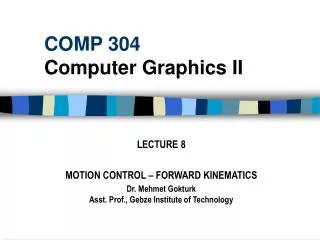
rd instruction memory PC registers rs Data memory rt ALU +4 imm 1. Instruction Fetch 2. Decode/ Register Read 3. Execute 4. Memory 5. Reg. Write Datapath: Generic Steps
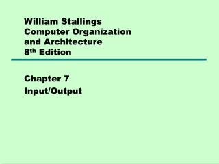
Datapath Walkthroughs • add $r3,$r1,$r2 # r3 = r1+r2 • Stage 1: fetch this instruction, inc. PC • Stage 2: decode to find it’s an add, then read registers $r1 and $r2 • Stage 3: add the two values retrieved in Stage 2 • Stage 4: idle (nothing to write to memory) • Stage 5: write result of Stage 3 into register $r3
3 1 instruction memory PC registers Data memory 2 ALU imm +4 add r3, r1, r2 reg[1]+reg[2] Example: ADD Instruction reg[1] reg[2]
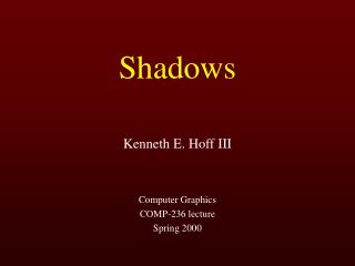
Datapath Walkthroughs (cont.) • slti $r3,$r1,17 • Stage 1: fetch this instruction, inc. PC • Stage 2: decode to find it’s an slti, then read register $r1 • Stage 3: compare value retrieved in Stage 2 with the integer 17 • Stage 4: go idle • Stage 5: write the result of Stage 3 in register $r3
x 1 instruction memory PC registers Data memory 3 ALU imm +4 reg[1] slti r3, r1, 17 reg[1]-17 17 Example: SLTI Instruction
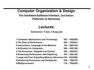
Datapath Walkthroughs (cont.) • sw $r3, 17($r1) • Stage 1: fetch this instruction, inc. PC • Stage 2: decode to find it’s a sw, then read registers $r1 and $r3 • Stage 3: add 17 to value in register $r1 (retrieved in Stage 2) • Stage 4: write value in register $r3 (retrieved in Stage 2) into memory address computed in Stage 3 • Stage 5: go idle (nothing to write into a register)
x 1 instruction memory PC registers Data memory 3 ALU imm +4 reg[1] SW r3, 17(r1) reg[3] reg[1]+17 17 MEM[r1+17]<-r3 Example: SW Instruction
Why Five Stages? • Could we have a different number of stages? • Yes, and other architectures do • So why does MIPS have five stages, if instructions tend to go idle for at least one stage? • There is one instruction that uses all five stages: the load
Why Five Stages? (cont.) • lw $r3, 17($r1) • Stage 1: fetch this instruction, inc. PC • Stage 2: decode to find it’s a lw, then read register $r1 • Stage 3: add 17 to value in register $r1 (retrieved in Stage 2) • Stage 4: read value from memory address compute in Stage 3 • Stage 5: write value found in Stage 4 into register $r3
reg[3] x 1 instruction memory PC registers Data memory 3 ALU imm +4 R3<-MEM[r1+17] reg[1] LW r3, 17(r1) reg[1]+17 17 Example: LW Instruction
What Hardware Is Needed? • PC: a register which keeps track of address of the next instruction. • General Purpose Registers • used in Stages 2 (read) and 5 (write) • we’re currently working with 32 of these • Memory • used in Stages 1 (fetch) and 4 (R/W) • cache system makes these two stages as fast as the others, on average
rd instruction memory PC registers rs Data memory ALU rt +4 imm opcode, funct Controller Datapath Summary • Construct datapath based on register transfers required to perform instructions. • Control part causes the right transfers to happen.
ALU ALU Control Where Is Logic Design Used? • Combinational circuits for ALU and other parts of the datapath. • Different control signals are needed for different clock cycles and different instructions for the ALU, registers and other parts of the datapath. Sequential circuits.
Start Instruction fetch/decode and register fetch R-type instructions Branch instruction Jump instruction Memory access instructions Where Is Logic Design Used? • High level view of finite state machine control. • Sequential logic design can be used to assert the correct control signals at the correct times.
Microprogramming • Instead of using the finite state machine, the control signals can also be stored as a sequence of (micro)instructions usually in a read-only memory (ROM) as a microprogram. • A microprogram counter and some additional logic can then be used to execute the sequence of microinstructions. • Popular in Complex Instruction Set Architectures (CISC) because complex instruction sets require complex controllers that can more easily be implemented as microprograms.
Things To Remember • Datapath is the hardware that performs operations necessary to execute programs. • Control instructs datapath on what to do next. • Datapath needs: • access to storage (general purpose registers and memory) • computational ability (ALU) • helper hardware (local registers and PC)
Things To Remember • Five stages of datapath (executing an instruction): • 1: Instruction Fetch (Increment PC) • 2: Instruction Decode (Read Registers) • 3: ALU (Computation) • 4: Memory Access • 5: Write to Registers • ALL instructions must go through ALL five stages. • Datapath designed in hardware.
Multiple Sources -- Single Sink 2 PC+4 instruction fetch rs+rt r-type instructions rs+sign_ex lw and sw instructions rs+sign_ex<<2 branch instruction
RegDst ALUSrcA IorD MemRead RegWrite control MemWrite ALUSrcB MemtoReg ALUOp Adding in the MUXs (and control points)
Control points RegDst: selects dest reg for write, selects rt (R-format) when 1 and “rd” (for lw) when 0 RegWrite: enables value to be written into register file ALUSrc: selects ALU source: either register file (for R-type) or an address coming from the 16 lower bits. MemToReg: Selects data source written into the register file: from memory (1) or from ALU output (0) MemRead: Active whenever memory read is required (ie lw). MemWrite: Active only on a memory write (ie sw) Branch: controls PCSrc to select input to the PC: either the next instruction or the branch address. ALUop1, ALUop2: Input to the ALU decode logic
An Alternative MultiCycle DataPath A-Bus • In each clock cycle, each Bus can be used to transfer from one source • µ-instruction can simply contain B-Bus and W-Dst fields B Bus A Reg File next PC P C inst mem IR mem S B ZX SX W-Bus
What about a 2-Bus Microarchitecture (datapath)? Instruction Fetch A-Bus B Bus A Reg File next PC P C IR S Mem M B ZX SX Decode / Operand Fetch A Reg File next PC P C IR S Mem M B ZX SX
Control Design of an ALU control circuit, in terms of the instruction Several layers of control
Memread ALUSrcA = 0 IorD = 0 ALUSrcA = 0 PCWrite IRWrite ALUSrcB = 11 PCSource=10 ALUSrcB = 01 ALUOp = 00 ALUOp = 00 PCWrite PCSource = 00 ALUSrcA = 1 ALUSrcB = 00 ALUOp = 01 PCWriteCond PCSource =01 ALUSrcA = 1 RegDst = 1 ALUSrcB = 00 RegWrite ALUOp = 10 MemtoReg=0 ALUSrcA = 1 RegDst = 0 ALUSrcB = 10 RegWrite ALUOp = 00 MemtoReg=1 State Machine 1.Instruction Fetch 2. Decode/Register Fetch Op=jump start Op=beq 5. Write Register Op=R-type 4. Mem Access 3. ALU MemWrite IorD=1 5. Write Register Op=lw/sw Op=sw MemRead IorD=1 Op=lw 3. ALU - Mem Addr Calc 4. Mem Access
Microprogramming • What are the “microinstructions” ?
Designing a Microinstruction Set • 1) Start with list of control signals • 2) Group signals together that make sense (vs. random): called “fields” • 3) Places fields in some logical order (e.g., ALU operation & ALU operands first and microinstruction sequencing last) • 4) Create a symbolic legend for the microinstruction format, showing name of field values and how they set the control signals • Use computers to design computers • 5) To minimize the width, encode operations that will never be used at the same time
“Macroinstruction” Interpretation User program plus Data this can change! Main Memory ADD SUB AND . . . one of these is mapped into one of these DATA execution unit AND microsequence e.g., Instr Fetch Decode/Reg Fetch Calculate (AND) Write register CPU control memory
Horizontal vs. Vertical Microprogramming Most microprogramming-based controllers vary between: Horizontal organization (1 control bit per control point) Vertical organization (fields encoded in the control memory and must be decoded to control something) NOTE: previous organization not TRUE horizontal microprogramming; register decoders: encoded microoperations Vertical + easier to program, not very different from programming a RISC machine - extra level of decoding may slow the machine down Horizontal + control potential parallelism of operations in the datapath - uses up lots of control store
Start w/ control signals, grouped into fields • Signal name Effect when deasserted Effect when assertedALUSelA 1st ALU operand = PC 1st ALU operand = Reg[rs]RegWrite None Reg. is written MemtoReg Reg. write data input = ALU Reg. write data input = memory RegDst Reg. dest. no. = rt Reg. dest. no. = rdMemRead None Memory at address is read, MDR <= Mem[addr]MemWrite None Memory at address is written IorD Memory address = PC Memory address = SIRWrite None IR <= MemoryPCWrite None PC <= PCSourcePCWriteCond None IF ALUzero then PC <= PCSourcePCSource PCSource = ALU PCSource = ALUout Single Bit Control Signal name Value EffectALUOp 00 ALU adds 01 ALU subtracts 10 ALU does function code 11 ALU does logical OR ALUSelB 000 2nd ALU input = Reg[rt] 001 2nd ALU input = 4 010 2nd ALU input = sign extended IR[15-0] 011 2nd ALU input = sign extended, shift left 2 IR[15-0] 100 2nd ALU input = zero extended IR[15-0] Multiple Bit Control
Legend of Fields and Symbolic Names • Field Name Values for Field Function of Field with Specific ValueALU Add ALU adds Subt. ALU subtracts Func code ALU does function code Or ALU does logical ORSRC1 PC 1st ALU input = PC rs 1st ALU input = Reg[rs]SRC2 4 2nd ALU input = 4 Extend 2nd ALU input = sign ext. IR[15-0] Extend0 2nd ALU input = zero ext. IR[15-0] Extshft 2nd ALU input = sign ex., sl IR[15-0] rt 2nd ALU input = Reg[rt]destination rd ALU Reg[rd] = ALUout rt ALU Reg[rt] = ALUout rt Mem Reg[rt] = Mem Memory Read PC Read memory using PC Read ALU Read memory using ALU output Write ALU Write memory using ALU outputMemory register IR IR = MemPC write ALU PC = ALU ALUoutCond IF ALU Zero then PC = ALUoutSequencing Seq Go to sequential µinstruction Fetch Go to the first microinstruction Dispatch Dispatch using ROM.
Microprogram it yourself! • LabelALU SRC1 SRC2 Dest. Memory Mem. Reg. PC Write Sequencing • Fetch: Add PC 4 Read PC IR ALU Seq Add PC Extshft Dispatch • Lw: Add rs Extend Seq Read ALU Seq rt MEM Fetch • Sw: Add rs Extend Seq Write ALU Fetch • Rtype: Func rs rt Seq rd ALU Fetch • Beq: Subt. rs rt ALUoutCond. Fetch • Ori: Or rs Extend0 Seq rt ALU Fetch