Download
1 / 24
240 likes | 365 Views
EUROCON 2005 The International Conference on "Computer as a tool“ November 21-24, 2005 Sava Center, Belgrade, Serbia & Montenegro. PSPICE Simulation of Two-Mass Vibratory Conveying System with Electromagnetic Drive. Zeljko V.Despotovic, Member, IEEE , Mihajlo Pupin Institute, Belgrade

E N D
EUROCON 2005The International Conference on "Computer as a tool“November 21-24, 2005Sava Center, Belgrade, Serbia & Montenegro PSPICE Simulation of Two-Mass Vibratory Conveying System with Electromagnetic Drive Zeljko V.Despotovic,Member, IEEE , Mihajlo Pupin Institute, Belgrade Zoran V.Stojiljkovic, School of Electrical Engineering, University of Belgrade
INTRODUCTION • Simulation model of two-mass Vibratory Conveying System (VCS) with Electromagnetic Vibratory Actuator (EVA) is presented in this paper • The model is set out on the basis of EVAand VCS conventional constructions, known in practice • The simulation model is created on the application program PSPICE • This generated model can be applied as an integral part of the simulation circuits of the power converters with phase and switch mode control, for driving vibratory actuator
The vibratory movements represent the most efficient way for granular and lump materials conveying Conveying process is based on a sequential throw movement of particles Vibrations of tank, i.e. of a“Load-Carrying Element” (LCE), in which the material is placed, induces the movement of material particles, so that they resemble to a highly viscous liquid and the material becomes easier for conveying LCE LCE
[1]I.F. Goncharevich, K.V. Frolov, and E.I.Rivin, Theory of vibratory technology,HemispherePublishingCorporation, New York, 1990, pp. 213-269 [2] E.M. Slot and N.P Kruyt,”Theoretical and experimental study of the transport of granular materials by inclined vibratory conveyors” Powder Technology, 87(3), 1996, pp.203-210 Due influences of many factors, process of conveyance by vibration of granular loads is very complicatedThe studies of physical process characteristics and establishment of conveyance speed dependence from parameters of the oscillating regime are exposed in [1], [2]
The conveying material flow directly depends on the average value of particles micro-throw, on a certainLCE working vibration frequency This average value, on the other hand, depends on vibratory width i.e. “peak to peak” amplitude oscillation, of the LCE Optimal transport for the most of materials is within frequency range 5Hz – 120 Hz and vibratory width range 0.1mm – 20mm LCE LCE
Types of Vibratory Conveying Systems Electromagnetic VCS are divided into two types: single-drive and multi-drive The single-drive systems can be one-, two- and three-mass The multiple-drive systems can be one-or multiple-mass
Electromagnetic actuators-ADVANTAGE • When a reciprocating motion has to be electrically produced, the use of a rotary electric motor, with a suitable transmission is really a rather roundabout way of solving the problem • It is generally a better solution to look for an incremental-motion system with magnetic coupling, so-called “Electromagnetic Vibratory Actuator” (EVA), which produces a direct “to-and-from” movement
Electromagnetic VCS - ADVANTAGE • Electromagnetic drives offer easy and simple control for the mass flow • The absence of wearing mechanical part, such as gears, cam belts, bearings, eccentrics or motors, make vibratory conveyors as most economical equipment • Application of electromagnetic vibratory drive in combination with power converter provides flexibility during work • It is possible to provide operation of VCS in the region of the mechanical resonance • Resonance is highly efficient, because large output displacement is provided by small input power • On this way, the whole conveying system has a behavior of the controllable mechanical oscillator
Previously mentioned facts were motivation for mathematical model formulation and creation PSPICE model of VCS with EVA
EVA presentation I.There is an electromagnet, whose armature is attracted in one direction, while the reverse stroke is completed by restoring elastic forces II.Electromagnet is energized from an AC source III.Reactive section is mounted on elastic system of springs IV.During each half period when the maximum value of the current is reached the armature is attracted, and at a small current value it is repelled as result of the restoring elastic forces in springs; therefore, vibratory frequency is double frequency of the power supply LCE Mechanical force f(t) , which is consequence of coil current and created by electromechanical conversion in EVA, is transmitted through the springs to the LCE V.These reactive vibrators can also operate on interrupted pulsating (DC) current; their frequency in this case depends on the pulsefrequency of the DC
Mathematical Model of EVA D+d >> x
Flexible elements, by which the LCE with material is supported, are composed of several leaf springs i.e. plate springs These elements are rigidly connected with the LCE on their one side; while on the other side, they are fitted to the base of the machine and sloped downunder define angle Referent direction of x-axis is normal to direction of the flexible elements We will assume that oscillations are made under exciting electromagnetic force f(t) in x-direction The system is started with oscillations from the static equilibrium state in which the already exists between gravitational and spring forces Description of one type of two-mass electromagnetic vibratory conveyor θ
Mechanical model of VCS • Model will be analyzed in a way that the mass of EVA reactive section is presented by m1, while mass m2constitutes a sum of masses (LCE, conveying material and the active section of EVA) • The mass m2 is a variable parameter within the system, because mass of the conveying material is varied under real conditions • Displacements of both masses m1 and m2 within an oscillatory system are described as x1 and x2, respectively • Equivalent stiffness of springs within EVA is denoted as k1, while equivalent stiffness of plate springs is denoted as k2 • Coefficient 1 describes mechanical losses and damping of the reactive part in EVA, while 2 is equivalent damping coefficient within transporting system (LCE with material)
Dynamical equations of the VCS : (1) (2) (3) (4) (5) x1 - x2 << D+d
Simulation circuit of VCS is created on the basis of previously derived differential equations. • Mechanical quantities are shown with equivalent electric quantities according table of electromechanical analogs for inverse system mass m<=>L inductance damping β <=>R resistance stiffness k <=>1/Ccapacitance-1
We have taken parameters of the actuator and vibratory system, which are usually occur in practice Load mass m2, which is oscillating, is adjusted to 98.5kg, so that the mechanical natural frequency of the system is equal to the AC source frequency 50Hz Simulation parameters
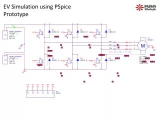
Simulation scheme for phase control mains ZCD outputs • Power thyristor is simulated as voltage-controlled switch S, with diode D in series. • Conducting moment of the switch S is determined by control voltage, synchronized with the moment of mains voltage zero-cross and phase shifted for angle .
Simulation results for phase angles.=126 and .=54Characteristic values: mains voltage-um, control voltage-uc, coil voltage-u, coil current–i and LCE displacement-x2.
Simulation scheme for switching control • From electrical standpoint, EVA is mostly inductive load by its nature, so generation of the sinusoidal half-wave current is possible by switching asymmetric half-bridge (dual forward) converter with current-mode control • EVA is driven from sinusoidal half-wave current, attained from tracking the reference sine half- wave with fd=50Hz. It has been simply realized with comparator tolerance band i.e. hysteresis (“bang-bang”) controller. • Reference current was compared with actual current with the tolerance band around the reference current.
Simulation results for switching controlCharacteristic values : coil current-i, switches current iS1, iS2, free-willing diodes currentiD1, iD2, switches control voltage uc, coil voltage- u and LCE displacement- x2. • EVA current waveform is very similar to the case with phase control • The only difference is in current high-frequency ripple due to the hysteresis control, which is in case of switching drive
Conclusion-phase control • In case of thyristor converter, with phase control, LCE displacement has “smooth” sine characteristic, although EVA current is pulsating • Change of vibratory width is due to change of phase angle (by decrease of phase angle, the effective voltage and coil current increase • This is caused by increase of the oscillation amplitude of LCE too, which is created by stronger impulse of exciting force;in opposite, increase of phase angle, cause decrease of the amplitude oscillation • Usage of thyristor converters with phase control implies constant vibratory frequency, which is imposed by supply mains. • Serious problem can appear due to change of conveying material mass even due to change of parameters of the supporting springs.
Conclusion-switching control • Switching converters can exceed these disadvantages. • In switching converter with tolerance band current control, EVA current is independent of mains frequency. • EVA current waveform is very similar to the case with phase control. • The only difference is in current high-frequency ripple due to the hysteresis control. • Drive current ripple doesn’t affect LCE oscillation waveform, since sine wave of displacement is “smooth”, like that of the thyristor drive.
References [1] I.F. Goncharevich, K.V. Frolov, and E.I.Rivin, Theory of vibratory technology, Hemisphere Publishing Corporation, New York, 1990, pp. 213-269. [2] E.M. Slot and N.P Kruyt, ”Theoretical and experimental study of the transport of granular materials by inclined vibratory conveyors”, Powder Technology, 87(3), 1996, pp.203-210. [3] M.A. Parameswaran and S.Ganapahy, ”Vibratory Conveying-Analysis and Design: A Review”, Mechanism and Machine Theory, Vol.14, No. 2, April 1979, pp. 89-97. [4] E.H. Werninck, “Electric Motor Handbook”, McGraw-HILL Book Company (UK) Limited, 1978, pp. 330-333. [5] M.Joshi, “Performance Monitoring System for Electromagnetic Vibrating Feeders of Coal Handling Plant”, Plant Maintenance Resource Center, M-News Edition 27, Technical paper at web site: www.plant-maintenance.com/articles/Feeder_Performance_Monitoring.pdf, July 2002. [6] T. Doi, K.Yoshida, Y.Tamai, K.Kono, K.Naito, and T.Ono, ”Feedback Control for Vibratory Feeder of Electromagnetic Type”, Proc. ICAM’98, 1998, pp. 849-854. [7] T. Doi, K.Yoshida, Y.Tamai, K.Kono, K.Naito, and T.Ono, “Modeling and Feedback Control for Vibratory Feeder of Electromagnetic Type”, Journal of Robotics and Mechatronics, Vol.11, No.5, June 1999, pp. 563-572. [8] Z. Despotovic, “Matematical model of electromagnetic vibratory actuator”, PROCEEDINGS (Vol.T3-3.2, pp 1-5) of the XII International Symposium of the Power Electronics, N. Sad 5-7. XI 2003. [9] S. Seely, “Electromechanical energy conversion”, McGraw-HILL Book Company INC., New York, 1962, pp.73-106.