Download
1 / 43
740 likes | 1.67k Views
NDT METHODS. Penetrant Inspection Magnetic Particle Inspection Eddy Current Inspection Ultrasonic Inspection Radiographic Inspection. Dye Penetrant Inspection. Surface breaking defects only detected Penetrant applied to the component and drawn into the defects by capillary action

E N D
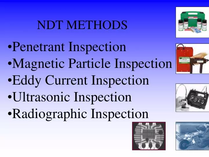
NDT METHODS • Penetrant Inspection • Magnetic Particle Inspection • Eddy Current Inspection • Ultrasonic Inspection • Radiographic Inspection
Dye Penetrant Inspection • Surface breaking defects only detected • Penetrant applied to the component and drawn into the defects by capillary action • Applicable to all non- porous and non absorbing materials. • Penetrants are available in many different types • Water washable contrast • Solvent removable contrast • Water washable fluorescent • Solvent removable fluorescent • Post-emulsifiable fluorescent
Dye Penetrant Inspection Step 1. Pre-Cleaning Cleaning preparation is very important on this method. Usually solvent removal is been used
Dye Penetrant Inspection Step 2. Apply penetrant After the application of the penetrant the penetrant is normally left on the components surface for approximately 15 minutes (dwell time). The penetrant enters any defects that may be present by capillary action
Dye Penetrant Inspection Step 3. Clean off penetrant After sufficient penetration time (dwell time) has been given,excess removal penetrant stage take place. A damped lint free tissue with solvent is used to clean the excess penetrant.
Dye Penetrant Inspection Step 3. Apply developer After the excess penetrant is been removed, a thin layer of developer is applied.A penetrant drawn out by reversed capillary action.
Dye Penetrant Inspection Step 4. Inspection / development time Inspection should take place immediately after the developer has been applied .Any defects present will show as a bleed out during development time.
Dye Penetrant Inspection Step 5. Post-Cleaning After the inspection has been performed post cleaning is required to prevent corrosion.
Dye Penetrant Inspection Fluorescent Penetrant Bleed out viewed under a UV-A light source Bleed out viewed under white light Colour contrast Penetrant
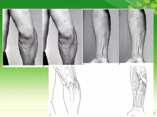
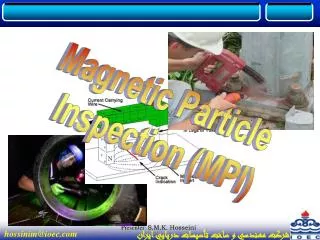
Magnetic Particle Inspection • Surface and slight sub-surface detection • Relies on magnetization of component being tested • Ferro-magnetic materials only can be tested • A magnetic field is introduced into a specimen being tested • Methods of applying a magnetic field, yolk, permanent magnet, prods and flexible cables. • Fine particles of iron powder are applied to the test area • Any defect which interrupts the magnetic field, will create a leakage field, which attracts the particles • Any defect will show up as either a dark indication or in the case of fluorescent particles under UV-A light a green/yellow indication
Electro-magnet (yolk) DC or AC Collection of ink particles due to leakage field Crack like indication Prods DC or AC Crack like indication Magnetic Particle Inspection
A crack like indication Magnetic Particle Inspection
Magnetic Particle Inspection Alternatively to contrast inks, fluorescent inks may be used for greater sensitivity. These inks require a UV-A light source and a darkened viewing area to inspect the component
Magnetic Particle Inspection Typical sequence of operations to inspect a weld • Clean area to be tested • Apply contrast paint • Apply magnetisism to the component • Apply ferro-magnetic ink to the component during magnetising • Interpret the test area • Post clean and de-magnatise if required
Magnetic Particle Inspection • Advantages • Simple to use • Inexpensive • Rapid results • Little surface preparation required • More sensitive than visual inspection • Disadvantages • Surface or slight sub-surface detection only • Magnetic materials only • No indication of defects depths • Detection is required in two directions
Basic Principles of Ultrasonic Testing • To understand and appreciate the capability and limitation of UT
Ultrasonic Inspection • Sub-surface detection • This detection method uses high frequency sound waves, typically above 2MHz to pass through a material • A probe is used which contains a piezo electric crystal to transmit and receive ultrasonic pulses and display the signals on a cathode ray tube or digital display • The actual display relates to the time taken for the ultrasonic pulses to travel the distance to the interface and back • An interface could be the back of a plate material or a defect • For ultrasound to enter a material a couplant must be introduced between the probe and specimen
Ultrasonic Inspection Ultrasonic testing is a good technique for the detection of plate laminations and thickness surveys Laminations detected using compression probes
defect echo Back wall echo initial pulse Material Thk Ultrasonic Inspection defect 0 10 20 30 40 50 Compression Probe CRT Display
Ultrasonic Inspection Pulse echo signals A scan Display UT Set, Digital Compression probe Thickness checking the material
Ultrasonic Inspection Ultrasonic testing requires high operator for defect identification Most weld defects detected using angle probes
Ultrasonic Inspection UT Set A Scan Display Angle Probe
Ultrasonic Inspection initial pulse defect echo Surface distance defect sound path 0 10 20 30 40 50 Angle Probe CRT Display
Ultrasonic Inspection • Advantages • Rapid results • Sub-surface detection • Safe • Can detect planar defect • Capable of measuring the depth of defects • May be battery powered • Portable • Disadvantages • Trained and skilled operator required • Requires high operator skill • Good surface finish required • Difficulty on detecting volumetric defect • Couplant may contaminate • No permanent record
Radiographic Inspection The principles of radiography • X or Gamma radiation is imposed upon a test object • Radiation is transmitted to varying degrees dependant upon the density of the material through which it is travelling • Thinner areas and materials of a less density show as darker areas on the radiograph • Thicker areas and materials of a greater density show as lighter areas on a radiograph • Applicable to metals,non-metals and composites
Industrial Radiography • Gamma Rays Generated by the decay of unstable atoms • X - Rays Electrically generated
Industrial Radiography • X - Rays Electrically generated
Industrial Radiography • Gamma Rays Generated by the decay of unstable atoms
TWI 10fe16 Radiographic Inspection Source Image quality indicator Radiation beam Test specimen Radiographic film
10fe16 Radiographic Inspection Source Image quality indicator Radiation beam 10fe16 Test specimen Radiographic film with latent image after exposure
7FE12 Radiographic Sensitivity Wire type IQI Step / Hole type IQI
Step/Hole Type IQI Wire Type IQI Image Quality Indicators
Radiographic Techniques • Single Wall Single Image (SWSI) - film inside, source outside • Single Wall Single Image (SWSI) panoramic - film outside, source inside (internal exposure) • Double Wall Single Image (DWSI) - film outside, source outside (external exposure) • Double Wall Double Image (DWDI) - film outside, source outside (elliptical exposure)
Film Single wall single image SWSI Film IQI’s should be placed source side
Film Single wall single image SWSI panoramic • IQI’s are placed on the film side • Source inside film outside (single exposure)
Double wall single image DWSI Film • IQI’s are placed on the film side • Source outside film outside (multiple exposure) • This technique is intended for pipe diameters over 100mm
Unique identification • IQI placing EN W10 A B • Pitch marks indicating readable film length ID MR11 Double wall single image DWSI Identification Radiograph
Film Double wall double image DWDI elliptical exposure • IQI’s are placed on the source or film side • Source outside film outside (multiple exposure) • A minimum of two exposures • This technique is intended for pipe diameters less than 100mm
4 3 • Unique identification • IQI placing EN W10 • Pitch marks indicating readable film length 1 2 ID MR12 Double wall double image DWDI Identification Shot A Radiograph
TWI Radiographic Inspection • Disadvantages • Expensive equipment • Bulky equipment ( x-ray ) • Harmful radiation • Detection on defect depending on orientation • Slow results • Required license to operate • Advantages • Permanent record • Little surface preparation • Defect identification • No material type limitation