Download
1 / 6
70 likes | 100 Views
IO/Column Redundancy Analysis . RedundancyAnalysis { ColumnSegmentRange { SegmentAddress [ y ] : AddressPort ( < name > ) ; . . //Repeat for all SegmentAddress bits . } ColumnSegment ( <SegmentName> ) { SegmentCountRange [ < lowRange > : < highRange > ] ; FuseSet {

E N D
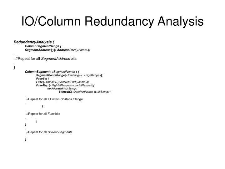
IO/Column Redundancy Analysis RedundancyAnalysis { ColumnSegmentRange { SegmentAddress [y]: AddressPort(<name>); . . //Repeat for all SegmentAddress bits . } ColumnSegment (<SegmentName>) { SegmentCountRange [<lowRange>: <highRange>]; FuseSet { Fuse [<bitIndex>]: AddressPort(<name>); FuseMap [<HighBitRange>:<LowBitRange>] { NotAllocated: <bitString>; ShiftedIO(<DataPortName>):<bitString>; . . //Repeat for all IO within ShiftedIORange . } . . //Repeat for all Fuse bits . } } . . //Repeat for all ColumnSegments . }
IO/Column Redundancy Analysis • Column-SegmentRange • define a portion of the memory address space where a spare element can replace one ormore defective elements. • SegmentAddress • specify which address ports are used to define the range of each memory segment. • ColumnSegment • define one or more segments of the memory space which have spare elements. • SegmentCountRange • define the lowRange and the highRange for the defined segment address bits. When a defective element is within this address range, a spare element can be allocated from this segment. • ShiftedIORange • define a group of IO/Data bits where spare elements can replace a faulty IO. When a defective element is within this group, a spare element can be allocated from this segment. • FuseSet • contains the information about the fuse register. The fuse register contains the bit mapping information for identifying the defective IO/Column. • Fuse Property • indicate the memory address ports to be logged in the fuse registers upon detecting failure. You must define the address port using the syntax: • Fuse[<bitIndex>]:AddressPort(<name>); • This property is optional for IO shift redundancy • FuseMap • define the HighBitRange and the LowBitRange for the fuse used to map the defective IO to the • corresponding fuse register value. FuseMap wrapper is independent of the Fuse property. • NotAllocated • specify the fuse register value that indicates no repair is needed for the column segment. If this property is not defined, an allocation bit is used as an indicator if repair is required, and a faulty IO information is logged. The allocation bit is the MSB bit of the Fuse Registers. • ShiftedIO • specify the values, to be logged in the fuse register which will uniquely identify each defective IO.
IO Redundancy Example(Parallel Repair port) Redundant IOs Left Half Right Half RepairEnableRight RepairEnableLeft IORepairRight[2:0] IORepairLeft{2:0] Control Circuitry IO Shift Circuit IO Shift Circuit Data[7:0] Data[15:8]
IO Redundancy Example RedundancyAnalysis { ColumnSegment (LEFT) { ShiftedIORange: Data[7:0]; FuseSet { FuseMap[2:0] { ShiftedIO(Data[0]): 3’b000; ShiftedIO(Data[1]): 3’b001; ShiftedIO(Data[2]): 3’b010; ShiftedIO(Data[3]): 3’b011; ShiftedIO(Data[4]): 3’b100; ShiftedIO(Data[5]): 3’b101; ShiftedIO(Data[6]): 3’b110; ShiftedIO(Data[7]): 3’b111; } } PinMap { SpareElement{ RepairEnable : RepairEnableLeft; FuseMap[0] : IORepairLeft[0]; FuseMap[1] : IORepairLeft[1]; FuseMap[2] : IORepairLeft[2]; } } }
IO Redundancy Example (cont) ColumnSegment (RIGHT) { ShiftedIORange: Data[15:8]; FuseSet { FuseMap[2:0] { ShiftedIO(Data[8]): 3’b000; ShiftedIO(Data[9]): 3’b001; ShiftedIO(Data[10]): 3’b010; ShiftedIO(Data[11]): 3’b011; ShiftedIO(Data[12]): 3’b100; ShiftedIO(Data[13]): 3’b101; ShiftedIO(Data[14]): 3’b110; ShiftedIO(Data[15]): 3’b111; } } PinMap { SpareElement{ RepairEnable : RepairEnableRight; FuseMap[0] : IORepairRight[0]; FuseMap[1] : IORepairRight[1]; FuseMap[2] : IORepairRight[2]; } } }
More Information • Similar syntax is used to describe Row redundancy • PinMap wrapper syntax is not different from IO PinMap • The Syntax is also used for Serial Repair Port • Replace IORepairX by RepairRegister[Y] • Room for imporvments