Download
1 / 1
10 likes | 116 Views
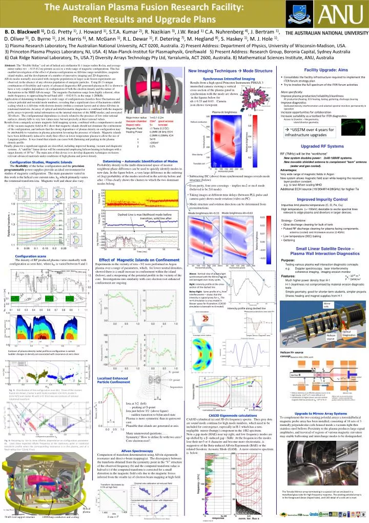
Helicon source.

E N D
Helicon source B. D. Blackwell 1), D.G. Pretty 1), J. Howard 1), S.T.A. Kumar 2), R. Nazikian3), J.W. Read 1)C.A. Nuhrenberg4), J. Bertram 1), D. Oliver 5), D. Byrne 1), J.H. Harris 6), M. McGann 1), R.L. Dewar 1), F. Detering 7), M. Hegland8), S. Haskey 1), M. J. Hole 1). 1) Plasma Research Laboratory, The Australian National University, ACT 0200, Australia.2) Present Address: Department of Physics, University of Wisconsin-Madison, USA. 3) Princeton Plasma Physics Laboratory, NJ, USA.4) Max-Planck-InstitutfürPlasmaphysik, Greifswald5) Present Address: Research Group, Boronia Capital, Sydney Australia 6) Oak Ridge National Laboratory, Tn, USA.7) Diversity Arrays Technology Pty Ltd, Yarralumla, ACT 2600, Australia.8) Mathematical Sciences Institute, ANU, Australia Abstract: The “flexible Heliac” coil set of helical axis stellarator H-1 (major radius R=1m, and average minor radius <r> ~ 0.15-0.2 m) permits access to a wide range of magnetic configurations. This has enabled investigation of the effect of plasma configuration on Alfvénic range instabilities, magnetic island studies, and the development of a number of innovative imaging and 2D diagnostics. Alfvén modes normally associated with energetic populations in larger scale fusion experiments are observed, in the absence of any obvious population of energetic particles. Using H-1’s unique combination of flexibility and variety of advanced diagnostics RF-generated plasma in H-1 is shown to have a very complex dependence on configuration of both the electron density and the nature of fluctuations in the MHD Alfvén range. The magnetic fluctuations range from highly coherent, often multi-frequency, to approaching broad-band (df/f ~ 0.02-0.5), in the range 1-200kHz. Application of datamining techniques to a wide range of configurations classifies these fluctuations and extracts poloidal and toroidal mode numbers, revealing that a significant class of fluctuations exhibit scaling which is i) Alfvénic with electron density (within a constant factor) and ii) shear Alfvénic in rotational transform. An array of optical and interferometric diagnostics is combined with the magnetic probe arrays to provide initial information on the internal structure of the MHD modes, and associated 3D effects. The configurational dependence is closely related to the presence of low order rational surfaces; density falls to very low values near, but not precisely at these rational values. Results from a uniquely accurate magnetic field mapping system, combined with a comprehensive model of the vacuum magnetic field in H-1 show that magnetic islands should not dominate the confinement of the configuration, and indicate that the strong dependence of plasma density on configuration may be attributable to variations in plasma generation favouring the presence of islands. Magnetic islands have been deliberately induced to study their effect on lower temperature plasma to allow the use of Langmuir probes. It was found that islands can cause both flattening and peaking in the plasma density profile. Finally, plans for a significant upgrade are described, including improved heating, vacuum and diagnostic systems. A “satellite” linear device will be constructed employing helicon heating in hydrogen with a target density of 1019m-3. The main aim of this device is to develop diagnostic techniques on fusion-relevant advanced materials under conditions of high plasma and power density. Facility Upgrade: Aims New Imaging Techniques Mode Structure • Consolidate the facility infrastructure required to implement the ITER forum strategy plan • Try to involve the full spectrum of the ITER forum activities More specifically: Improve plasma production/reliability/cleanliness RF production/heating, ECH heating, baking, gettering, discharge cleaning Improve diagnostics Dedicated density interferometers and selected spectral monitors permanently in operation Increase opportunities for collaboration Increasie suitability as a testbed for ITER diagnostics Access to Divertor – like geometry,island divertor geometry Synchronous Intensified Imaging • Results from a high speed Princeton Instruments PIMAX 3 intensified camera viewing a vertical cross-section of the plasma gated in synchronism with the mode are shown in the figures below for κh = 0.33 and 0.63. Cameraicon shows viewpoint. Major/minor radius 1m/0.1-0.2m Vacuum chamber 33m2 good access Aspect ratio 5+ toroidal Magnetic Field 1 Tesla (0.2 DC) Heating Power 0.2MW 28 GHz ECH 0.3MW 6-25MHz ICH n3e18 T<200eV 0.2% ~US$7M over 4 years for infrastructure upgrades Upgraded RF Systems RF (7MHz) will be the “workhorse” New system doubles power: 2x40-180kW systems. New movable shielded antenna to complement “bare” antenna (water and gas cooled). Advantages: Very wide range of magnetic fields in Argon New system allows magnetic field scan while keeping the resonant layer position constant.e.g. to test Alfven scaling MHD Additional ECH source (10/30kW14/28GHz) for higher Te Datamining – Automatic Identification of Modes • Probability density in the multi-dimensional space of nearest neighbour phase difference can be used to quickly identify modes in new data. In the figure below, a very large difference in the ordering of (log) probability of the modes involved in the activity before and after ~37ms clearly shows the clusters to which the two dominant modes belong. Configuration Studies, Magnetic Islands The flexibility of the heliac configuration and the precision programmable power supplies provide an ideal environment for studies of magnetic configuration. The main parameter varied in this work is the helical core current ratio, kH which primarily varies the rotational transform iota. Magnetic well and shear also vary . The Australian Plasma Fusion Research Facility: Recent Results and Upgrade Plans • Subtracting DC (above) from synchronized images reveals mode structure (below). • Even parity, four zero crossings – implies m=2 or m=4 mode (believed to be 5/4 mode). • Taking images at different time delays (between PLL pulse and camera gate) shows mode rotation (video on PC) • Mode structure and rotation direction can be determined from reconstructions. Improved Impurity Control Impurities limit plasma temperature (C, O, Fe, Cu) High temperature (>~100eV) desirable to excite spectral lines relevant to edge plasma and divertors in larger devices. Strategy - Combine: • Glow discharge cleaning for bulk of tank • Pulsed RF discharge cleaning for plasma facing components. • antenna (cooled) and microwave source (2.4GHz) • Low temperature (90C) baking • Gettering Dashed Line is max likelihood mode before transition, solid line after Small Linear Satellite Device – Plasma Wall Interaction Diagnostics Configuration scans The density of RF produced plasma varies markedly with configuration as seen here, where kHis varied between 0 and 1. Effect of Magnetic Islands on Confinement • Experiments in the vicinity of iota ~3/2 were performed in Argon plasma over a range of parameters, which, for lower neutral densities, showed there is a small increase in confinement within the island (below), and a steepening of the potential profile in the vicinity of the core. Investigations into similarity with core electron root enhanced confinement are ongoing. Purpose: Testing various plasma wall interaction diagnostic concepts e.g. Doppler spectroscopy, laser interferometry coherence imaging, imaging erosion monitor Features: Much higher power density than H-1 H-1 cleanliness not compromised by material erosion diagnostic tests Simple geometry, good for shorter-term students, simpler projects Shares heating and magnet supplies from H-1 Above: Vertical view of plasma light synchronised with the Mirnov signals and averaged over many cycles. Right: Intensity profile at the cross-section of the dashed line Below Right: Same profile of ne from interferometer – shows that the intensity is a good proxy for ne. The m=4 simulation is a toy model in Boozer space for illustration. (CAS3D simulation is beneath m=4 model) ne ~ 1019 m-3 P ~ 1MW/m2 Mirror coils Intensity profile along dashed line Optical Diagnostics Contours of plasma density radial profile as configuration is varied:Sudden changes in density are associated with resonance at zero shear Helicon H+ source concept Localised Enhanced Particle Confinement Fig. 5: Classification of the configuration scan (kh). Three of the clusters found are shown, Cluster 6 with mode numbers n/m=5/4, cluster 5 (n/m=4/3) and cluster 46 with n=0. thin lines are contours of rational rotational transform Iota at 3/2 (left) – peaking at O-point Iota just below 3/2 (above figure) – sudden transition to bifurcated state Plasma is more symmetric than in quiescent case. Plausible that islands are generated at axis. Many unanswered questions……Symmetry? How to define Er with two axes? Core electron root?. Upgrade to Mirnov Array Systems • To complement the two existing poloidal arrays a toroidal/helical magnetic probe array has been installed, consisting of 16 sets of 3 mutually perpendicular coils housed inside a vacuum-tight thin stainless steel bellows Proximity to the plasma produces large signal amplitudes, and traversal of regions of various magnetic curvature may enable ballooning and interchange modes to be distinguished. CAS3D Eigenmode calculations • CAS3D cylindrical (a) and 3D (b) frequency spectra. They grey dots are sound mode continua for high mode numbers, which need to be included for convergence, especially in H-1 which has a non-negligible mirror (bumpy) component in the 1/B2 spectrum. • Note a gap mode (HAE) near top right, and low frequency modes are up-shifted by a -induced gap ~5kHz At the frequencies the modes lose their m=3 or 4 character and become more electrostatic, is suggestive of the Beta-induced Alfvén Eigenmode (BAE) or the related Geodesic Acoustic Mode (GAM). A more extensive spectrum is below. Fig. 6: Rescaling by ne to show Alfvénic dependence on configuration parameter kh. Lines show expected Alfvén frequency at the stationary point in rotational transform profile when the corresponding resonance is in the plasma, and at a fixed radius (<a>~15cm) if not. Alfven Spectroscopy • Comparison of transform determination using Alfvén eigenmode resonance and direct e-beam mapping(a). The discrepancy between the transform obtained from the symmetry point in the “V” structure of the observed frequency (b) and the computed transform value is halved (c) if the computed transform is corrected for a small distortion in the magnetic field coils due to the magnetic forces inferred from the results (a) of electron beam mapping at high field. The Toroidal Mirnov array terminating in a special coil set enclosed in a metallised glass tube for high frequency response. The existing poloidal array is in the foreground (bean shaped tube), and CAD detail of a coils set is inset. Helical plasma by John Wach 50 kN /coil support structure 14000Amp conductors and cooling