Download
1 / 23
230 likes | 355 Views
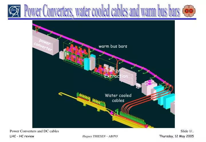
Power Converters, water cooled cables and warm bus bars. power converter. warm bus bars. Energy Extraction. Water cooled cables. Introduction. 1. Power converter reception tests and installation DC cable reception tests and installation Warm power tests without superconducting magnets

E N D
Power Converters, water cooled cables and warm bus bars power converter warm bus bars Energy Extraction Water cooled cables
Introduction • 1. Power converter reception tests and installation • DC cable reception tests and installation • Warm power tests without superconducting magnets • Cold power tests with superconducting magnets • Conclusion
Point 4 SR5 RR53 SR4 UA47 RR57 Point 5 UA43 SR6 UA63 UJ33 Point 6 B e a m d u m p USC55 Point 3 UJ56 UA67 SR: Thyristor PCs for the warm magnets SR3 UA27 ARC: 60A corrector PCs SR2 SR7 RR73 BA4 UA23 RR: 2kA PCs 600A PCs SR8 S P S SR1 BA7 Point 7 UA83 Point 2 SM18 UA87 RR77 RR17 RR13 T I 2 UA: 3.25kA and 2kA PCs 600A and 120A PCs MB PCs Point 8 I n j e c t i o n T I 8 Point 1 UJ16 UJ14 I n j e c t i o n LHC Power Converters • 1700 converters with 98% underground • 750*60A corrector converters (0.5kW) • 740*120A&600A converters • 220*2kA&3.25kA converters • 8*13kA MB converters (2.6MW)
Power Part (Voltage Source) AC Mains Supply Cooling System DC cables Intk Magnet DC cables Power Interlock Controller Vref FGC WorldFIP (Iref) Dcct LHC Power Converters LHC Power Converter
Converter Integration at CERN Surface Halls Individual Tests at manufacturer premises Individual Tests at CERN Surface Halls Power Part Power Part (Voltage source) Power Part (Voltage source) FGC Dcct FGC FGC LHC Power Converter (Current source) : Performance validation Dcct Dcct Power converter reception tests Power converter tests before installation
PC installation Power converters installation • the power converters are transported and installed in the tunnel without to be dismantled…
PC installation Power converters installation … except the main dipole power converter 2.2 m 40 t Installation tests • By the specialists • In parallel with the • short circuit tests 11 m
DC cables Installation and tests Water cooled cable tests and installation • The water cooled cables are not tested at CERN before their installation • After their installation, the water cooled cables are only tested • in pressure : 24 bars, 10 minutes • in insulation : 3 kV DC with current leakage measurement
Powering circuit Cooling system DC cable intk DC cables Power Converter AC Main supply Magnet Energy Extraction Ctrl Room Intk syst Warm power tests (EDMS 464458 & 573115) Cold power tests (EDMS 519716)
Warm power tests 8 hours heat run tests for superconducting circuits • The objectives of this test are to valid • AC connexion of the power converter • Installation of power converter • Cooling of the DC cables • DC connexions between power converter, DC cables and discharge system • The magnet is replaced by a short circuit piece Hardware commissioning procedure EDMS 575406
Warm power tests 8 hours heat run tests for superconducting circuits • Requests • AC distribution • UPS • Water cooling system • Ventilation system • Short circuit pieces • Energy extraction system for the 13kA and 600A with EE • PIC for the 13kA
Warm power tests 8 hours heat run tests for warm magnets • The objectives of this test are to valid • AC connexion of the power converter • Installation of power converter • DC connexions between power converter, DC cables and magnet • Set up of the current loop • Power converter performance • For transfer line power converters, the TI8 procedure is used
Warm power tests 8 hours heat run tests for warm magnets • Requests • AC network • Interlock system • Magnet
Warm power tests Interlock tests • The objectives of this test are to valid • Connexion between the interlock system and the power converter • Comportment of the different system (power converter, interlock system and energy extraction system) Control Test • The objectives of this test are to valid • The WorldFIP (MUGEF for TL-PC) • The Field Control Room softwares • The Alarm system, Logging system and Post Mortem system
Warm power tests 24 hours heat run test for superconducting circuits • The objectives of this tests are to valid • Global water cooling system • Global air conditioning system • Global AC distribution • Global control of power converters by the FCR
Warm power tests Sector 78 10 weeks for a sector • 5 weeks for an UA • 3 weeks for a RR • 2 weeks for an arc
Cold power tests (EDMS 519716) Circuit type tests (60A, 120A, etc…) • First Powering tests (at minimum stable current) • Check the start of the power converter • Set up of current loop and verify the stability • Safety system • Intermediate current • Verify the current loop stability • Safety system • Nominal current • Power converter performance in current source
Cold power tests Main dipole circuits • Main issues with the RB circuits • Starting of the power converter (> 20 s to go to the minimum current) • Setting current loop (noise of the current measurement) • Discharge system in the odd point • Recuperation mode • Safety system • Power converter performance in current source
6 kA 6 kA Cold power tests MQM circuits • Main issues with the MQM circuits • Starting of the 2 power converters • Setting current loop and verify the performance (resistive coupling) • Safety system
Iref1 RST Vref1 - Ipc1 Vref2 Ipc1 7 kA Vref3 Decoupling system Iref2 RST Ipc2 - Ipc3 Ipc2 ±600 A 4.7 kA 7 kA Ipc3 Iref3 RST - 7 kA Cold power tests Inner Triplet main quadrupole circuits (EDMS 531773)
7 kA ±600 A 4.7 kA 7 kA 7 kA Cold power tests Inner Triplet main quadrupole circuits • Test strategy • Test the 5 kA circuit alone (inner power converter) • Test the 7 kA circuit alone (outer power converter) • Test the 5 kA + 7 kA with decoupling loop • Test the 5 kA + 7 kA + 0.6 kA with decoupling loop • Set up of the current loops
Cold power tests First sector: 14 days for the 3 main circuits 16 days for the IT circuits 8 days for the other circuits Other sector: 7 days for the 3 main circuits 8 days for the IT circuits 4 days for the other circuits
Conclusions 1. The power converters are tested before their installation but theses tests are limited not real load not real environment not with the other systems (PIC and WorldFIP) 2. The DC cables are not tested before their installation not tests in power 3. The main circuits (RB and RQ) and Inner Triplet request a special attention