Download
1 / 27
270 likes | 273 Views
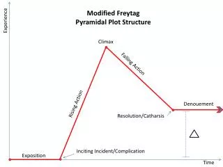
EXPERIENCE. Adherence to National Industry Standards, Procedures and Guidelines. Motor and Pump Base Foundational Repair. Foundational failure is one of the most common factors leading to vibration in the pumps and motors.

E N D
EXPERIENCE • Adherence to National Industry Standards, Procedures and Guidelines
Foundational failure is one of the most common factors leading to vibration in the pumps and motors If foundational failures are not addressed, you will experience significant particle and coupling wear which may result in premature replacement and unscheduled shut downs
Equipment Anchor Points Substantial amounts of force are placed on footpads and equipment anchor points These areas are usually the most affected by grout pack deterioration and create voids or ‘Soft Foot’ due to steel stress and result in vibration and unsound foundations
Foundational Failures Can Occur From • Inferior material composition at time of pour • Cracked or deteriorating grout packing and concrete due to service Corroding reinforcing steel in the basin due to improper instillation Chemical attack to the basin
Previous Vibratory Solution Methods Included Shimming the Anchor Areas Although this method has been widely accepted for aligning the Pump and Motors it may have adverse affects when related to vibration • If the Machine Level is out of alignment It is recommended to Mill to near perfect conditions • This method is only recommended if you have taken steps to ensure the Foundation and Soul Plate are Sound
REPAIR OPTIONS FOR RESTORATION • Structural repair using reinforcing steel bars • Water control (Leak Sealing) • Epoxy Pressure Injection • Pump and Motor base grout removal & repair • This can be lengthy and typically not the best option • Soil Stabilization • Void Fills • Demo and Replace • Laser level weld up and mill down
Applications Machinery base repairs Pump and motor base repair Exciter basins Structural support base repair Basin cracks Pedestal restoration Epoxy/Urethane pressure injection method STRUCTURAL REPAIR
Solutions • EPOXY INJECTION: • Low Viscosity • Moisture Insensitive • Easy Application • Must be done under pressure • Extreme High Strength • 12,000 PSI epoxy materials are available on the market • Chemical Resistance • 100% Solids • This means 0% Shrinkage
Epoxy Injection Basin Repair Epoxies consist of 2 or more blended components to make a material specifically designed for certain applications including chemical resistance, compressive strength Epoxies used for grout pack solidification and basin injection have a tested compressive strength ranging from 8,500 psi (when applied at 73°f and 1 day cure) to 12,000 psi (at 73°f and 3-28 day full cure) • The injection method is minimally invasive requiring holes to be drilled in hollowed locations and can be pumped under high or low pressure • It is recommended that BOTH the motor and pump are removed
Epoxy Injection Issues- • EPOXY INJECTION: • Cannot be used in flowing water • May not fully penetrate cracks if viscosity is high or if the wrong material is selected • Chemical attacks can be prevalent • Temperature limitations • Typically less than 350º F • Proper cure time MUST be given to reach ‘working time’
Epoxy Injection Basin Repair – Select the right material! In June 2011, under request from nuclear customers, the injection epoxies were tested by an independent Engineering consultant. Upon selecting a qualified engineering and testing company, the goal was to ensure and validate the proper material compressive strength as indicated under the specifications. Three samples were submitted and machined into cylindrical shape prior to testing. A compression machine as specified by ASTM D695-10 Section 5.1 was utilized. Load was applied to each specimen in accordance with ASTM D695-10 Section 9.2. Results Testing was stopped once the 3- day strength requirement of 10,000 PSI had been met. All three specimens had achieved greater than the desired 10,000 PSI with one sample achieving 15,035 PSI. At the applied load, the specimens had been compressed to a height of 0.33-0.37 inches with a diameter of 0.85-0.90 inches. Upon observation, no cracking was found. As well, the specimens began to rebound slowly after the load was removed. Within 1 hour the specimens had rebounded between 57% and 66% of their original height. Within 24 hours, all specimens had rebounded approximately 98% of their original test height.
Epoxy Injection Basin Repair Where Can Epoxy Injections Be Performed? Pump Basins Sole Plates Exciter Basins Concrete Foundations Structural Reinforcement Applications Reinforcing Steel Corrosion Mitigation
Repair sealantcapabilities: Thin enough to penetrate “hairline” cracks Work in flowing water Bond to wet surfaces Remain flexible and inert after quick curing Safe in Potable water situations WATER CONTROL Urethane Injection Process Solution for problems such as: • Freeze / thaw damage • Corrosion of reinforcing steel • Erosion of the structure • Mineral deposits • Loss of dry environment
WATER CONTROL • URETHANE GROUT INJECTION: • Cost Effective • Non-Toxic • Single component capability • Void Fill Capability - Vertical and Horizontal • Can be used as a flexible joint ,gasket or pressure seal • No Down Time - Work can be completed while components are online • Stops water intrusion in cracks, joints and pipe penetrations • Can be used in NSF potable water applications
BENEFITS OF CONCRETE & COMPOSITE REPAIR • RESOLVES VIBRATION PROBLEMS • STOPS WATER LEAKAGE • STOPS REBAR EXPANSION • REPAIRS SURFACES • SOIL STABILIZATIONS (PERMIABLE SOILS) • SUB BASEMENTS ARE VERY PRONE TO SOIL SHRINKAGE ESPECIALLY NEAR WATER SOURCES e.g RIVERS/RESEVIORS • REPAIRS PIPING, TANKS ,ELIMINATES COSTLY SHUT DOWNS OR REPLACEMENTS • MAINTENANCE -ADDS LIFE TO THE STRUCTURE • SAFETY
ONLINE LEAK SEALING • Original developers ofon-line leak repair services in the 1920’s • Leak repair for steam,hydrocarbons, gas, air,chemicals and liquids • Engineering solutions for leaksfrom 1600 F to cryogenic • Leak repair from vacuum up to 6300 PSI • Sub-Sea leak sealing
LEAK SEALING APPLICATIONS • Holes in pipes or valves • Cracked welds • Packing glands • Flange leaks • Valve bonnets • Threaded fittings • Exchanger leaks • Pressure seal valves • Turbine horizontal joints
Introduction Plant Components Plant components repaired by leak sealing include: • Flanges • Valves Glands • Bolted Valve Bonnets • Pressure Seal Bonnets • Straight Pipe • Elbows • Tees • Valve Bodies • Expansion Joints (bellows) • Heat Exchangers • Pressure Vessels • Nozzles on Vessels • Ball Valves • Transformers • Wellheads • Turbines (half joints) • Floating Tank Roofs • Insulation Joints (electrical)
Standard Applications – Leaks from Valve Glands Leaks from Valve Glands Typical Injection Points in Valve Glands:
Standard Applications Bolted Flange / Gasket Leaks
Standard Applications – Leaks from Pipes and Piping Components Clamp Arrangements Piping Configurations (some examples):