Download
1 / 23
230 likes | 390 Views
Skyworker Preliminary Design Review. William “Red” Whittaker Peter Staritz Chris Urmson. Field Robotics Center September 10, 1999. Space Solar Power (SSP) Facilities. Constellation of SSP satellites in GEO 1GW of energy to the ground via a microwave transmission antenna 1 km in diameter

E N D
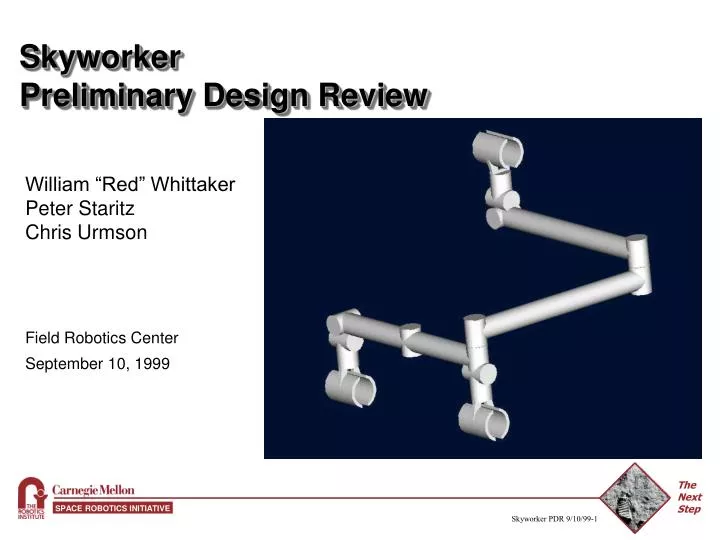
SkyworkerPreliminary Design Review William “Red” Whittaker Peter Staritz Chris Urmson Field Robotics Center September 10, 1999
Space Solar Power (SSP) Facilities • Constellation of SSP satellites in GEO • 1GW of energy to the ground via a microwave transmission antenna 1 km in diameter • 150m wide and 10 to 15 kilometers in length • Mass of 4800 MT (10X as massive as ISS) • Assembled over 1 year, maintained for 30 years • Need for robotic systems capable of Assembly, Inspection, and Maintenance (AIM) tasks
SSP Facility AIM • Solar array • Assembled through automated docking and deployment • Microwave antenna • Requires completion of complicated assembly tasks • Joining of deployable truss sections • Attaching transmitter elements • Coupling Power Management and Distribution (PMAD) system • Entire facility will benefit from automated inspection and maintenance capabilities
FY99 FY00 FY01 FY02 FY03 FY04 FY05 FY06 FY07 FY08 FY09 FY10 FY11 FY12 FY13 FY14 FY15 FY16 FY17 FY18 FY19 FY20 Space Solar PowerAutomated Technology Roadmap < 2000 2001-2005 2006-2010 2011-2015 2016-2020 single axis ED thruster in uwave field Air-bearing precision maneuvering Tether and Antenna Front Plane Maneuvering Demonstration Electrodynamic Propulsion Systems LEGEND Robust control w/ attached robot interaction Learning/adapta-tion for unknown payloads&failure Demo terminal guidance sensing system Trajectory planning and optimization R&D Result-Driven Decision Point 90% Reliable Fly-to-grapple and Robust Abort Autonomous Rendevous and Dock Major R&D Prm Milestone 80% Reliable Fly-to-grapple and Robust Abort Stable Posture and gait control w/ 4 cooperating truss walkers Joint failure compensation and increased structural disturbance Strategic Program Objective Payload balancing w/ 6 cooperating truss walkers Robust locomotion and free flyer interaction in dynamic environment Force and Redundancy Control Strategies for Cooperative Systems Perform mating tasks w/ 4 cooperating truss walkers & flex. structure Force-controlled free flyer payload exchange Integrate high-bandwidth optical flow, range, and force to improve grasp reliability Identify feducial mark scheme to simplify vision Develop compact flight hardware implementation of high-rate vision algorithms Sensing/Perception Locate standard grabrail fixture under nominal conditions Demonstrate strategies to mitigate lighting effects Borrowed from Automated Assembly, Maintenance, and Operations of a Space Solar Power System
FY99 FY00 FY01 FY02 FY03 FY04 FY05 FY06 FY07 FY08 FY09 FY10 FY11 FY12 FY13 FY14 FY15 FY16 FY17 FY18 FY19 FY20 Space Solar PowerAutomated Technology Roadmap < 2000 2001-2005 2006-2010 2011-2015 2016-2020 Demo automated Ground Segment operations inc. power sales Simulation and visualization of assembly activity Demo automated Space Segment operations inc. maintenance flights Demonstrate 100% automation of space and ground segment operations Assembly and Maintenance Planning Assembly activity planning for 4 cooperating truss walkers Assembly activity planning for 4 cooperating truss walkers + free flyer On-orbit multi. walker antenna assembly demonstration Multi. walker/free-flyer antenna repair in neutral buoyancy Autonomous grasp and locomotion of antenna element On-orbit walker/free flyer antenna assembly and repair demo Integrated Technology Demos Prototype neutral buoyancy truss walker FY05 Decision on first flight demo Multi. walker automated antenna assembly in neutral buoyancy LEGEND R&D Result-Driven Decision Point Major R&D Pgm Milestone Strategic Program Objective Borrowed from Automated Assembly, Maintenance, and Operations of a Space Solar Power System
Objectives • Demonstrate the viability of using robots for orbital construction • Prove the validity of using structure walkers for orbital AIM • Demonstrate SSP AIM relevant tasks using robotics • Simulate prospective SSP AIM robots and tasks
Representative Tasks • Walk, turn, and transition across planes on a truss structure • Pick up and place a payload at arbitrary locations and orientations in space • Carry a payload while walking, turning, and transitioning • Conduct calibration and inspection tasks • Connect power and communications cables • Cooperatively carry massive or large payloads • Perform tasks that require multiple robot collaboration
Demonstration • Prototype Robot • Pick up and carry a model transmitting element the length of the truss, turn while carrying, couple the element to the structure • Connect Power Management and Distribution (PMAD) to the element • Perform a mock calibration • Simulation • Large scale construction utilizing multiple robots • Coordinated installation of full scale transmitting elements • Demonstrate extended lifetime operations
Program Philosophies • Design for Earth based demonstration, but always maintain a path to orbital application • Accept a baseline environment (structure, tasks, etc..) • Leverage heritage technologies when available • Design and manufacture in house whenever possible • Consider physical scalability of design • Ensure robust software operation through incremental testing of components • Maintain software scalability through Object Oriented Principles
Configuration - Key Metrics • Control Complexity • The number of joints that must be actuated in synchrony • Continuous Motion • System supports a gait in which the payload can maintain a constant velocity • How difficult it is to control that gait • Cost • DOF, links, grippers, sensors, control complexity, gravity compensation • Compatibility with gravity compensation • Possible to compensate with available resources, new system or recycled heritage system • Forces exerted / Forces experienced • Maximum forces and torques experience/exerted by the robot
Configuration - Key Metrics (Cont.) • Workspace • Effective working volume with one gripper attached to the structure • Energy Consumption • The energy consumed by the machine to move a specified distance and speed with a given payload • DOF • Total number of joints • Number of different joint types • Mass • DOF, links, grippers, sensors, constants • Layout of available volume • Sufficient room for onboard components
N-type • Key Features • Walking posture • Manipulating posture • Sufficient internal volume to allow tetherless operation • Fine motion / Transition Joint • Inchworm Gait • Cable Mating
Configuration N-type • Control Complexity • At most 4 joints must operate in synchrony for standard gait • Continuous Motion • System supports a continuous gait • Simplified gait, uncertainties in only one dimension • Cost • Lowest number of total components affecting cost • Compatibility with GC • Compatible with heritage system, only minor modifications needed • Forces Exerted / Forces Experienced • Normal stride exerts/experiences minimal torques
Configuration N-type • Workspace • N-type “unfolds” to become a 3 link manipulator • Energy Consumption • Continuous gait and fewer motors needed for standard stride result in lower consumption • DOF • 11 joints, 3 grippers • Mass • ~35 kilograms • Layout of available volume • Sufficient room for onboard components
Gripper Design Issues • Skyworker will move its own mass in addition to a payload • Increased possibility of truss failure due to point loads • Gripper faces will be extended and shaped to match the structure (reducing point loads) • Rotation about the longeron is a possibility • High coefficient of friction coatings • Simple structure detection is necessary • Proximity sensors (capaciflectors)
Joints • 3 Joint types • 3 Axial revolute joints • 2 Offset revolute joint • 6 Inline revolute joints
Force Analysis • Concept of “Walking lightly” • Largest forces occur during a standard stride as opposed to during acceleration • 2 forms of force analysis • Further analysis will minimize the torque generated by the base joints • Forces: • Payload Inertia • Arm’s Inertia • Given: • -Payload Velocity • -Payload acceleration
B D A C Maximum Torques
Gravity Compensation • Allows for maneuvers not possible in normal gravity • Passive compensation • Counterweight system • Transmission • 10:1 ratio • Active X-Y table • Heritage system
Power Electronics • Tetherless operations • 20 minute demonstration • Less than 40 watt-hours of energy at a peak rate of 120W +/- 30% • Mass Constraint • 3kg (batteries/charger/converters) • Volume Constraint
Battery Recharging • Onboard Charging Solution • Power obtained through special gripper • Contact with electrified terminal on demonstration structure • Inductively Coupled Charging a future possibility • All charging electronics/distribution onboard • Battery Monitoring System • Automatically detects when charge is necessary • Returns to ‘Charging Station’ when needed • Disconnects and returns to work when fully recharged
Battery Technologies • Batteries we considered: • NiCd batteries selected for prototype, different battery technology may be used in space applications.