Download
1 / 42
420 likes | 541 Views
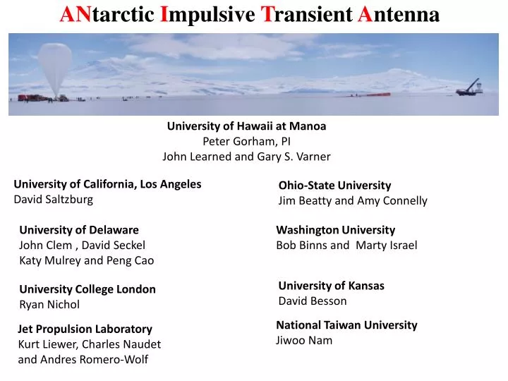
AN tarctic I mpulsive T ransient A ntenna. University of Hawaii at Manoa Peter Gorham, PI John Learned and Gary S. Varner. University of California, Los Angeles David Saltzburg. Ohio-State University Jim Beatty and Amy Connelly. University of Delaware John Clem , David Seckel

E N D
ANtarcticImpulsive Transient Antenna University of Hawaii at Manoa Peter Gorham, PI John Learned and Gary S. Varner University of California, Los Angeles David Saltzburg Ohio-State University Jim Beatty and Amy Connelly University of Delaware John Clem , David Seckel Katy Mulrey and Peng Cao Washington University Bob Binnsand Marty Israel University of Kansas David Besson University College London Ryan Nichol National Taiwan University JiwooNam Jet Propulsion Laboratory Kurt Liewer, Charles Naudet and Andres Romero-Wolf
What can we learn from studying EeV neutrinos? If GZK (Greisen–Zatsepin–Kuzmin) process is the source of the UHE cutoff UHECR propagate through intergalactic space filled with the 3K cosmic microwave background radiation blue shifted to GeV gamma in CM frame UHE neutrinos may be observed as byproducts of the GZK process, or they may be observed from the same astrophysical sources that produce UHECR. UHECR provide only local source information Cosmic Acceleratorslikely to evolve in many ways: strength, metallicity, number density, … GZK neutrino spectra are direct from sources at all epochs
How can we measure EeV neutrinos? Detection of neutrinos requires a target for conversion of the UHE neutrino to a high-energy particle cascade, followed by observation of electromagnetic radiation signatures of the particle cascade. Particle cascades result in an evolving population of electrons, positrons, and photons. – Positrons are depleted by in-flight annihilation. – Additional electrons are upscattered from the medium. – The net effect is a negative charge excess (~20%) in the shower moving relativistically. Coherent Cherenkov Radiation at long wavelengths! At smaller wavelengths, Cherenkov light experiences destructive interference from electrons at different parts of the shower. Shower “Shower” is actually a thin disk of HE particles A few mm thick and few cm wide in solids At radio wavelengths longer than ~10-20 cm: appears as a single charge of Z~108 Z2=1016 x single e- Askaryan effect: coherent Cherenkov light
Askaryan emission from two simulations for a 100 TeV primary neutrino As the observation moves away from the Cerenkov angle, the frequency cutoff amplitude.
Select materials with long attenuation lengths in the RF have been tested at SLAC in a photon and electron beams. silica salt ice “Askaryan” effect have been confirm in these materials
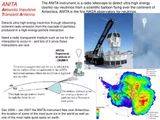
For ANITA, the target is the Antarctic ice, which is observed from balloon altitudes. The combination of the Antarctic polar vortex, providing excellent coverage of the large areas of very deep ice, and the remarkable radio-frequency clarity of ice leads to ANITA’s essential methodology: A radio-triggered waveform recorder using an antenna array to observe nearly the entire lower hemisphere, with an effective target of order a million cubic km of ice in view at any time. The radio emission from a neutrino-initiated cascade is beamed into a radio-Cherenkov ring, which must then point toward ANITA’s direction for detection ANITA field of view
Polarization Cerenkov is linearly polarized perpendicular to cascade momentum and wave front Askaryan signals originating in the ice strongly favor vertical polarization Only top of the cone escapes total internal reflection
Seavey, dual-polarized horn antennas provide superb impulse response & bandwidth
ANITA 1 Instrument Broadband (0.2~1.2GHz) Antenna Array (Dual-polarized horn antennas) A photograph of the ANITA 1 balloon payload before launch in December 2006, along with labels which indicate various important components of the experiment.
ANITA 1 Trigger/ Digitizer Data Stream Dual signal path: 1 for trigger and 1 for digitization Use multiple frequency bands for trigger Trigger Pattern requires > 3 antennas in both upper/lower rings (100-200kHz@Level1 trig.) Digitizer only runs when triggered to save power
ANITA-I Flight At float (38km) (Photo by James Roth) Launch (Dec 15 2006) Landing Successful flight during 2006-2007 austral summer 35 days, 3.5 orbits 8.2M events recorded, 17.25 days of total cumulative live time
ANITA Borehole TX Calibration Ground Based Pulser System System Verification Trigger Test Propagation and Surface Timing / Angular Resolution Surface TX RF(200-300km) Ice Pulser Amplitude vs. distance Clear borehole pulse on event display and Trigger Pattern
zenith 0.2o azimuth 0.8o Angular Resolution (Bore Hole Pulse Events) Payload position During this segment Reconstructed RF source positions Excellent angular resolution
T = L / c Plane wave t (up-down) RF direction Event Reconstruction Angular reconstruction is a crucial part in the ANITA data analysis. Powerful background rejection Incoherent thermal events (99% of data set) Anthropogenic RF events from existing bases Angular reconstruction using Interferometry.
ANITA 2 Instrument Dec 2008
Limits from IceCube and ANITA-2, along with, expected sensitivity for ANITA-3+4 for a combined 100 days, and a wide range flux model predictions for cosmogenic neutrinos.
Neutrino signals vs. EAS signals V-pol predominate after refraction ANITA • Neutrino Detection • RF Cherenkov by Askaryan Effect • Low Frenelcoeff. for tranverse electric waves at the air-ice boundary. • H-pol signal supressed • Predominately V-pol Geomagnetic Field • EAS Detection • H-pol predominate RF signal by geosynchrotron emission • V-pol component is further suppressed in the reflection • Predominately H-pol Cosmic Ray ANITA Synchrotron Emission (H-pol.) RF Cherenkov neutrino EAS Shower ~10m length (20% e- excess)
The analysis of the data from ANITA’s first flight found no neutrinos, but it did reveal a significant above-background signal of horizontally polarized events The measured signal polarizations in comparison to known geomagnetic field angles to show that the detected events have the signature of geosynchrotron emission. Measured polarization angle versus geomagnetic field angle, where the geomagnetic field angle has been modified by the vertical and horizontal Fresnel components for the angle of reflection observed in each event. The green line represents polarization along the direction of the Lorentz force
Preliminary results from the SLAC T-510 experiment. A 1 kGaussvertical magnetic field is applied to an EM shower in dielectric producing a horizontally-polarized pulse that is otherwise absent. The beam pattern of the pulse is in good agreement with current simulations.
ANITA 3 Hang Test 8/7/2014 48 New Seavey Horns 180- 1200 MHz band Horizontal and Vertical Polarization Trigger Ultra-light-weight deployable low-frequency quad-slot Hpol antenna with sensitivity over the 30-80 MHz band.
Trigger/ Digitizer Data Stream Dual signal path: 1 for trigger and 1 for digitization Use multiple frequency bands for trigger Trigger Pattern requires > 3 antennas in both upper/lower rings (100-200kHz@Level1 trig.) Digitizer only runs when triggered to save power
Data Analysis for Neutrino Hunting Blinding analysis to avoid biases, blinding 90% of data, use 10% for background study Event selection criteria (1) Plane wave reconstruction (reject thermal noise) (2) Impulsive event selection (3) Anthropogenic background rejection -isolated from camps, isolated from other evnets (4) V-pol dominant event selection Signal efficiency on data analysis is about 80%. An example of impulsive event
ANITA 3 An incident neutrino interacting in the Antarctic ice would emit a radio Cherenkov signal which would be refracted at the surface and observed at the payload, up to 700km away. 48 dual-polarization radio antennas (180-1200 MHz)
Net negative charge: Askaryan effect G. Askar´yan, Soviet Phys. JETP 14, 441 (1962) • “Entrainment” of electrons from the medium as shower penetrates Excess negative charge develops (electrons) → • Main interactions contributing: Moeller Compton “Low” energy processes ~ MeV atomic atomic e+ annhilation Bhabha G.A. Askaryan Askaryan effect confirmed in SLAC experiments atomic Askaryan effect present in any medium with bound electrons (for instance in air).
ANITA Concept • UHE Cosmic Ray Detection • EAS with Geo-synchrotron radiation • Handful number of events of UHE • Large field of view • Partially coherent emission in ANITA’s frequency band (0.2~1.2GHz) . • UHE Neutrino Detection • Radio Cherenkov signals in Antarctic ice. • Excellent sensitivity in 1019- 5x10²⁰ eV. • Large volumes of ice • Excellent transparency of the Antarctic ice (RF attenuation length: ~ 1km.)