Download
1 / 18
190 likes | 374 Views
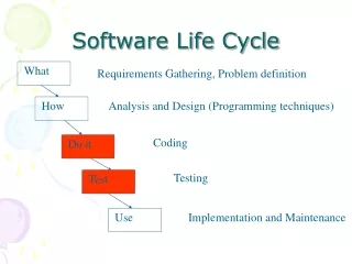
Art for Chapter 12, Software Life Cycle. Figure 12-1. Simple life cycle for software development (UML use case diagram). Figure 12-2. Simple life cycle for software development (UML activity diagram). Figure 12-3. Another simple life cycle (UML activity diagram).

E N D
Figure 12-1. Simple life cycle for software development (UML use case diagram).
Figure 12-2. Simple life cycle for software development (UML activity diagram).
Figure 12-3. Another simple life cycle (UML activity diagram).
Figure 12-4. Entity-centered view of software development (UML class diagram).
Figure 12-5. Activities and products of the simple life cycle of Figure 12-2 (UML class diagram).
Figure 12-6. Model of the software life cycle (UML class diagram). A software life cycle consists of process groups, which in turn consist of processes. A process accomplishes a specific purpose (e.g., requirements, design, installation). A process consists of activities, which are in turn consists of sub-activities or tasks. Tasks represent the smallest piece of work that is relevant to management. Tasks consume resources and produces one or more work products. A project is an instance of a software life cycle.
Figure 12-7. Process interrelationships in the IEEE 1074 standard (UML activity diagram, adapted from [IEEE Std. 1074-1995]]. As suggested by this picture, dependencies among processes and activities are complex and seldom allow a sequential execution of processes.
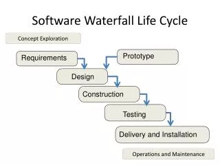
Figure 12-8. The waterfall model of software development is an activity-centered view of the software life cycle: Software development activities are performed in sequence (UML activity diagram adapted from [Royse, 1970] using IEEE 1074 names; project management and cross-development processes are omitted).
System Requirements Preliminary Analysis Design System Requirements Review Preliminary Design Review System Design Detailed Design System Design Review Critical Design Review (CDR) Software Requirements Analysis Software Specification Review CSC Coding & Integration CSU Testing & Testing … Figure 12-9. Waterfall model for the DOD Standard 2167A (UML activity diagram). Note activities specific to the DOD are used instead of IEEE 1074 activities. Decision points denote reviews: The subsequent activity is initiated only if the review is successful.
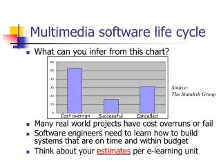
Figure 12-11. Boehm’s spiral model (Adapted from [Boehm, 1987]). The distance from the origin represents the cost accumulated by the project. The angle from the horizontal represents the type of activity. For example, the project P1 is currently in the risk analysis activity associated with software requirements. The project P2 is in the development of the system product design.
Figure 12-12. Sawtooth Model with two prototype demonstrations (UML activity diagram). The Client swimlane encloses the activities that are visible to the client, whereas the Developer swimlane encloses the activities that are at a lower abstraction level.
Figure 12-13. Shark tooth model with two prototype demonstrations and 1 review (UML activity diagram, levels of abstraction are represented with swimlanes). Small teeth reaching the management swimlane are internal reviews involving a prototype demo by the developers for the project manager. Large teeth reaching the client swimlane are prototype demonstrations to the client.
Figure 12-14. Entity-centered life cycle view of the models of the Unified Process (UML class diagram). the dependencies depict traceability. There are dependencies between all models. Only the dependencies between the use case model and the other models are shown [Jacobson et al., 1999].
Figure 12-15. Snapshot of a project issue base (UML object diagram). Issues i1 and i5 have been resolved, whereas all other issues are still open. Dependencies among issues indicate that the resolution of an issue can constraint the alternatives for dependent issues.
Figure 12-16. The waterfall model as a special case of the issue-based life cycle model (UML object diagram). All issues that belong to the same issue category are contained in the same UML package. In the project status shown in the figure, all the requirements elicitation and analysis issues have been closed; that is, the requirements elicitation and analysis activities have been completed.
Figure 12-17. In a complex project state, all activities can still have some open issues, which means that all activities need to be managed concurrently.