Download
1 / 13
140 likes | 348 Views
A Direct Digital Frequency Synthesizer Using A New ROM Compression Method. Byung-Do Yang, Ki-Hyuk Sung, Young-Joon Kim, Lee-Sup Kim, Seon-Ho Han*, and Hyun-Kyu Yu* Department of EECS, KAIST, 373-1 Kusong-dong, Yusong-gu, Taejon, 305-701, KOREA

E N D
A Direct Digital Frequency Synthesizer Using A New ROM Compression Method Byung-Do Yang, Ki-Hyuk Sung, Young-Joon Kim, Lee-Sup Kim, Seon-Ho Han*, and Hyun-Kyu Yu* Department of EECS, KAIST, 373-1 Kusong-dong, Yusong-gu, Taejon, 305-701, KOREA *ETRI, 161 Kajong-dong, Yusong-gu, Taejon, 305-350, KOREA bdyang@mvlsi.kaist.ac.kr Presenter:梁正勳 Number:97662003
Outline • Introduction • Background • A new ROM compression method • Chip Implementation and Performance • Conclusion
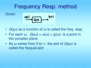
Introduction • The frequency synthesizers are conventionally based on phase locked loop (PLL). PLL-based frequency synthesizers generate sine waves with high spectral purity. • PLL-based frequency synthesizers are not suitable for the communication systems providing fast frequency switching and high frequency resolution. • The conventional DDFS uses a ROM table to store the amplitude of a quarter sine wave. • But, a large ROM table to store more data increases the size and the power dissipation. • Therefore, most of techniques for the DDFS have focused to reduce the size of the ROM table.
Background N bit frequency input word Δφ is added to an overflowing N-bit accumulator in each clock frequency fclk . output frequency minimum frequency resolution output sequence
Background • The DDFS in Fig. 1 uses a well-known technique which stores π / 2 rad of sine information instead of 2π rad using sine function symmetry to generate the full range sine wave. • The most significant bit determines the required sign of the result and the second most significant bit determines whether the amplitude is increasing or decreasing. • The remaining p-2 bits of the output bits of the accumulator are used to address a onequadrant sine lookup table.
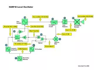
A new ROM compression method The quantization ROM (Q-ROM) stores some MSB bits of each ROM, and the error ROM (E-ROM) stores errors between the original ROM and the Q-ROM. The Q-ROM stores only one q bit quantized data per a section so that the Q-ROM address is reduced to 2i from 2k. If the required bits to store the maximum value among theerrors are e bits, the E-ROM size becomes 2k × e bits.
A new ROM compression method The Q-ROM stores only q bits instead of the output bits of the coarse ROM. The E-ROM stores errors between the coarse ROM and the Q-ROM.
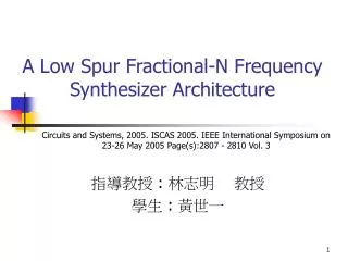
A new ROM compression method The total ROM size ( 2i × q + 2k × e bits)for the Q-ROM and the E-ROM. The parameters (i, q, and e) can be found by using the following algorithm in Fig. 4.
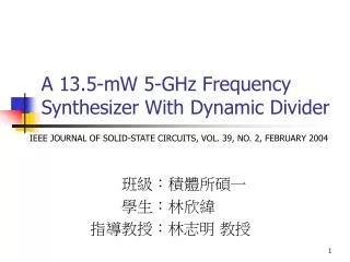
Conclusion • It divides each ROM in the conventional DDFS into two ROMs by a new ROM compression algorithm. • The total size of the ROMs in the proposed DDFS is significantly reduced compared to the original ROM. • The ROM compression ratio of 78 is achieved for a DDFS with 12bit output. • HSPICE simulation shows that the power dissipation is 9.56mW at 100MHz with 3.3V and the maximum clock frequency is 500MHz.
The End Thank you for your attentions !