Download
1 / 27
270 likes | 273 Views
This study focuses on understanding hydrogen release in a confined area, including stratification during release and diffusion mechanisms after release. Testing facility description, measurement techniques, experimental program, and results are discussed.

E N D
Large-Scale Hydrogen Release In An Isothermal Confined AreaJ.M. LACOME – Y. DAGBA – D. JAMOIS – L. PERRETTE- C. PROUSTICHS- San Sebastian, sept 2007
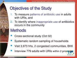
OBJECTIVES : • Study confined moderate releases of hydrogen : • Hydrogen stratification in the room during release depending upon release flow rate and release diameter (subsonic releases) • And diffusion mechanisms when release stops (in quiescent atmosphere) • Based upon concentration mapping and video recording • In order to better predict when hydrogen explosive atmospheres may occur
CONTENT • Test facility description : • Experimental set up • Measurement techniques • Experimental Program • Results and discussion • Conclusion
TestChamber measurement points (1 to 16) Isothermal and supposed tight
Th1 P1 "sevran 1" Release orifice Release orifice at the centre of the room T3 Release velocity: release orifice P3 Mass flow control: sonic nozzle P2,T2 PID NH4Cl droplets H 2 P diaph. 265 mm V1 V3 V2 120 mm HCl conc NH3 aq conc P1,T1 Pressure and temperature measurement
Measurements O2 controllers • Accuracy: • O2 = 0.02% vol. • gas = 1.5 % rel. • Flow: • 2 l/mn • 2 mm tube • 9 m long • transients 5-10 sec 3 analysers for 12 measurements points with a period of 80s (for 4 measurements)
Helium release seeded with NH4Cl nanometric droplets Seeding to see... Mirror Gas seeding device Rotating mirror Argon laser Controlled flow of Hydrogen With He only and without O2 sensors
Experimental Programme H2 release - Realistic flow rate for moderate up to relatively severe subsonic hydrogen release - Up to 4 hours test duration (release and diffusion phase) - Indirect H2 concentration measurement with O2 controllers - No laser and no video recording (safety concerns)
Experimental Programme He release - Volumetric flow rate conservation: same as H2 releases - Some tests with seeding and video recording to visualise the He rich atmosphere pattern but no O2 measurements (pollution concerns) - Some tests with indirect He concentration measurement (O2 controllers) - Up to 4 hours test duration (release and diffusion phase)
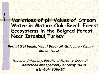
First phase: Subsonic jet and stratification - convective flow - short time scale 120 s 235 s 10 s He - 1,84 g/s - 4 minutes
Second phase: Diffusion - Diffusive flow - large time scale 4 min 160 min 85 min Diffusion: several hours
Variation of %H2 at different heights, 1m40 aside from release Results for a 1g/s H2 release through a 20 mm hole during 240 s and subsequent diffusion phase during 2 hours
Variation of %H2 at various sampling points located at the ceiling Typical results for a 1g/s H2 release through a 20 mm hole during 240 s
20% 18% 16% 14% 12% 10% 8% 6% 4% 2% 0% 0 1000 2000 3000 4000 Variation of %H2 in the jet axis Results for a 1g/s H2 release through a 20 mm hole during 240 s Volumic fraction of H2 (v/v) position 1 position 13 position 14 position 16 5000 6000 7000 Time (s)
2,4% 2,2% 2,0% 1,8% 1,6% 1,4% Gas concentration (%v/v) 1,2% position 6 1,0% Homogeneous mixing concentration 0,8% position 8 0,6% position 9 0,4% position 10 0,2% position 11 0,0% position 12 0 20 40 60 80 100 120 140 160 180 200 220 240 Variation of %H2 at different heights, 1m40 aside from release Results for a 200mg/s H2 release through a 5 mm hole during 240 s Time (minutes)
Concentration Profiles at 240 s for various subsonic releases 1m40 aside from release
H2 - 1 g/s - 20mm - 240s He - 1,84 g/s - 20mm - 240s Similarity between H2 and He at same flow rate (in mole)
Experimental achievements • mass control of small leakages • released gas visualisation with large tomography • multiport gas sampling • Physical analysis • practical study of stratification process • study of large scale hydrogen molecular diffusion • observations on He / H2 similarities • Numerical modelling • Data used for CFD benchmark (HySafe) • Perspectives • Deeper study of ventilation effects • Supersonic releases in confined volume
-(Dr/r .g. hi)0.5 D.S.Dcsup/hi Pos 6 Pos 8 Pos 9 Vi/hi Pos 10 -D.S.Dcinf/hi Pos 11 Pos 12 Simulated holes Modelling hydrogen concentration in the chamber Variable : holes surface Equivalent leak area between 90 and 170 cm2
Mass flow rate and velocity at orifice Comparison between measured velocity and calculated velocity with Cd = 0.68