Download
1 / 11
110 likes | 281 Views
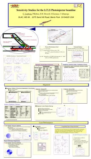
The NPS SRF Photoinjector. John W. Lewellen for the NPS-FEL Team Naval Postgraduate School Monterey, CA 93943. Acknowledgements & Thanks. NPS-FEL Team: Joe Blau, Keith Cohn, Bill Colson, John Harris, Brian Rusnak, Todd Smith, Rich Swent,

E N D
The NPS SRF Photoinjector John W. Lewellen for the NPS-FEL Team Naval Postgraduate School Monterey, CA 93943
Acknowledgements & Thanks • NPS-FEL Team: Joe Blau, Keith Cohn, Bill Colson, John Harris, Brian Rusnak, Todd Smith, Rich Swent, • Collaborators: Mark Curtin, Terry Grimm, Bill Graves, Bob Legg • Too many people to mention individually at Argonne, Boeing, JLab, LANL, Niowave • Meeting organizers • The Office of Naval Research • The High-Energy Laser Joint Technology Office
Outline • What is the NPS SRF Photoinjector? • Why are we building it? • What is it supposed to do? • What is the present status? • Where are we going with this?
Why are we building it? • Prototype of a 500-MHz quarter-wave cavity SRF photoinjector • Why a quarter-wave structure? • High transit-time factor (~l/7 gap) • High on-cathode gradient for exit beam energy • Compact size for resonant frequency • Why a prototype? • At lower cost: • Validate the beam dynamics • Learn the design “gotcha!”s • Reduce the development cycle time (1 year concept-to-RF)
What Does “Prototype” Mean? • No cavity tuners – close, but not right on, 500 MHz • Small He volume – have to refill frequently, or use an external tank • Metal cathode, no load-lock • “Simple” on-axis power coupler & cathode stalk designs • Low average beam power (100-W RF source)
Beam Voltage vs. Launch Phase High transit-time factor + high on-cathode gradient Good platform for novel cathode testing, e.g. field emitters
What’s the Present Status? • We have had two runs at Niowave so far • cathode not installed • up to ~ 700 kV gap voltage • made runs at reduced temperature: behavior as expected • Beamline under construction • Preparing for 1st runs with cathode stalk installed
What’s the Eventual Goal? • Source for exploring nC-range bunch charge dynamics in compact ERL lattices • merge optics • CSR studies • halo formation • Flexible platform for cathode testing • Driver / beam source for cavity characterization • 10-mA NPS-FEL Linac Injector • 10 pC – 1 nC bunch charge @ up to 100 MHz
Project Pathway • Prototype • Mk. I • single-bunch • not tunable • no loadlock • NPS-FEL Source • Mk. II • 1 – 10 mA • tunable • loadlock build new • NPS-FEL Source • Mk. I mod A • 1 – 10 mA • tunable • loadlock rebuild upgrade