Download
1 / 18
230 likes | 427 Views
Review Doppler Radar (Fig. 3.1) A simplified block diagram. Electric field incident on scatterer. Reflected electric field incident on antenna. Voltage input to the synchronous detectors; This pair of detectors shifts the frequency f to 0. jQ (t). A o.

E N D
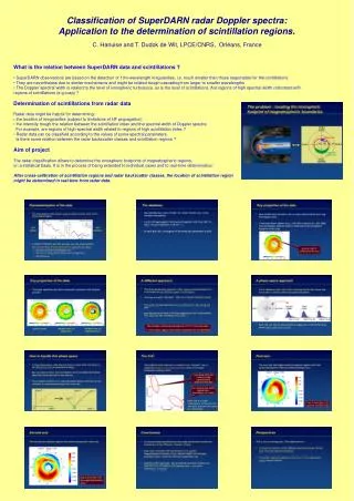
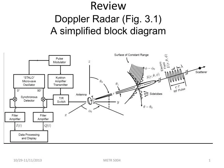
ReviewDoppler Radar (Fig. 3.1)A simplified block diagram METR 5004
Electric field incident on scatterer Reflected electric field incident on antenna Voltage input to the synchronous detectors; This pair of detectors shifts the frequency f to 0 jQ(t) Ao Echo voltage Voat the output of the detectors and filters . The echo amplitude is Ao and phase is ψe I(t) If the range r of the scatterer is fixed, the phasor (Ao, ψe) is fixed (i.e., no change in Ao nor ψe. But if scatterer has a radial velocity, phasor (Ao, ψe) rotates about the origin at the Doppler frequency fd. Complex plane (Phasor diagram)
1 μ s Range-Time 2 3 1 0 4 5 4 3 5 0 2 1 Stationary Moving (A) scatterers scatterer (B) METR 5004
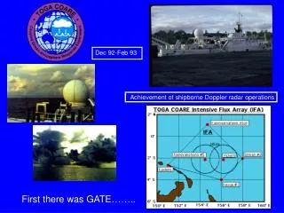
r=cτs/2 cτ λ Pulsed Radar Principle c = speed of microwaves = ch for H and = cv for V waves τ = pulse length λ = wavelength = λh for H and λv for V waves τs = time delay between transmission of a pulse and reception of an echo. METR 5004
Angular Beam Formation(the transition from a circular beam of constant diameter to an angular beam of constant angular width) Fresnel zone Far field region θ1= 1.27 λ/D (radians) METR 5004
Antenna (directive) Gaingt The defining equation: Eq. (3.4) (W m-2) = Power density incident on a scatterer r= range to measurement (m) = radiation pattern = 1 on beam axis = transmitted power (W) METR 5004
Backscattering Cross Section, σbfor a Spherical Particle METR 5004
Backscattered Power Density Incident on Receiving Antenna METR 5004
Echo Power PrReceived (3.20) Aeis the effective area of the receiving antenna for radiation from the θ,φ direction. It is shown that: (3.21) If the transmitting antenna is the same as the receiving antenna then: METR 5004
The Radar Equation(point scatterer/discrete object) METR 5004
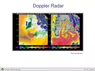
nth pulse (n+1)th pulse Ts time Apparent delay < Ts True delay > Ts Unambiguous Range ra • If targets are located beyond ra = cTs/2, their echoes from the nth transmitted pulse are received after the (n+1)th pulse is transmitted. Thus, they appear to be closer to the radar than they really are! • This is known as range folding • Ts = PRT • Unambiguous range: ra = cTs/2 • Echoes from scatterers between 0 and raare called 1st trip echoes, • Echoes from scatterers between ra and 2ra are called 2nd trip echoes, Echoes from scatterers between 2ra and 3ra are called 3rd trip echoes, etc ra METR 5004
Δr= vrTs is the change in range of the scatterer between successive transmitted pulses METR 5004
Another PRT Trade-Off • Correlation of pairs: • This is a measure of signal coherency • Accurate measurement of power requires long PRTs • More independent samples (low coherency) • But accurate measurement of velocity requires short PRTs • High correlation between sample pairs (high coherency) • Yet a large number of independent sample pairs are required METR 5004
Signal Coherency • How large a Ts can we pick? • Correlation between m = 1 pairs of echo samples is: • Correlated pairs: (i.e., Spectrum width must be much smaller than unambiguous velocity va = λ/4Ts) • Increasing Ts decreases correlation exponentially • also increases exponentially! • Pick a threshold: • Violation of this condition results in very large errors of estimates! METR 5004
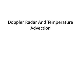
8 m s-1 Signal Coherency and Ambiguities • Range and velocity dilemma: rava=cl/8 • Signal coherency: sv<va /p • raconstraint: Eq. (7.2c) • This is a more basic constraint on radar parameters than the first equation above • Then, sv and not va imposes a basiclimitation on Doppler weather radars • Example: Severe storms have a median sv ~ 4 m/s and 10% of the time sv > 8 m/s. If we want accurate Dopplerestimates 90% of the time with a 10-cmradar (l = 10 cm); then, ra ≤ 150 km. This will often result in range ambiguities Fig. 7.5 150 km Spectrum width σv METR 5004 Unambiguous range ra
Echoes (I or Q) from Distributed Scatterers (Fig. 4.1) t c(s)≈ t (t = transmitted pulse width) mTs Weather signals (echoes) METR 5004
Weather Echo Statistics (Fig. 4.4) METR 5004
Reflectivity Factor Z(Spherical scatterers; Rayleigh condition: D≤ λ/16) METR 5004