Download
1 / 33
330 likes | 498 Views
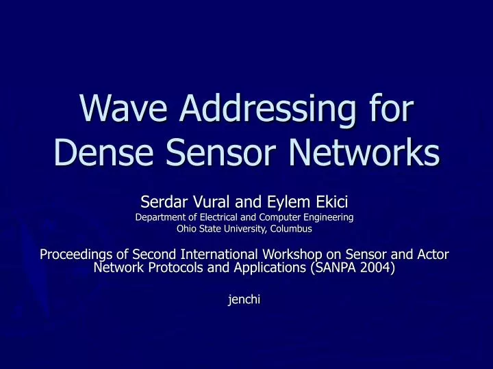
Wave Addressing for Dense Sensor Networks. Serdar Vural and Eylem Ekici Department of Electrical and Computer Engineering Ohio State University, Columbus Proceedings of Second International Workshop on Sensor and Actor Network Protocols and Applications (SANPA 2004) jenchi. Outline.

E N D
Wave Addressing for Dense Sensor Networks Serdar Vural and Eylem Ekici Department of Electrical and Computer Engineering Ohio State University, Columbus Proceedings of Second International Workshop on Sensor and Actor Network Protocols and Applications (SANPA 2004) jenchi
Outline • Introduction • The WADS Mechanism (Wave Addressing for Dense Sensor networks) • Wave Source Selection • Wave Propagation and Region Generation • Address Ambiguity Elimination • Performance Evaluation • Conclusion
Introduction • Various techniques have been proposed to determine the location of sensor nodes • Using GPS • Increase the cost of nodes • Fast depletion of limited energy sources • Signal strength measurement • Increased complexity of sensor nodes
Introduction • However, many application can tolerate higher level of uncertainty in location information • Intrusion detection • Interception applications • It is not necessary to implement costly, energy-inefficient, and infrastructure-reliant localization schemes that provide high fidelity localization
Introduction • Objective of this paper • To introduce Wave Addressingfor Dense SensorNetworks (WADS) method • To form a coordinate system called Wave Mapping Coordinate (WMC) • Without requiring specialized hardware in sensor nodes or infrastructure support in the network
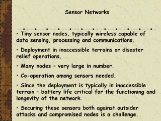
The WADS mechanism • System Description and Assumptions • To assume that the sensing application requires densely and randomly deployed sensor nodes in the sensing field • Sensor nodes • Identical communication capabilities • No mobility • No synchronization
The WADS mechanism • WADS operation • To create the WMC system using the hop distance of sensors from two randomly selected sensor nodes (wave sources) • Every node in the network receives two wave IDs • Note that region IDs do not belong to a single sensor nodes but to a set of sensor nodes in the same locality
8 hops 10 hops The WADS mechanism
The WADS mechanism • WMC system is accomplished in three steps • Wave Source Selection • Wave Propagation and Region Generation • Address Ambiguity Elimination
Address Ambiguity Elimination C (8,10)
Wave Source Selection • To select the sensor nodes that will serve as the two reference points in the network • Two possible wave source deployment scenarios • Pre-deployment selection • Two wave sources must be placed sufficiently separated from each other • Post-deployment selection • Since the sensor network is large, it is easier to use simpler distributed algorithms that incurs lower overhead
Wave Source Selection — Post-deployment selection • Every sensor generates two numbers • A random number (ID) • determines if it is a potential candidate for the first or second wave source • A random number Nwait between 0 and Nmax • Nmax determines the maximum delay tolerance of the system for WMC system generation • Sensor waits for T = Tturn X Nwait , where Tturn is the unit time period, which is in the order of the delay of a packet that would travel the maximum diameter of the network
Wave Source Selection — Post-deployment selection • Once there two numbers are generated, the sensor starts waiting until • It receives an ID from another wave source with the same source ID (1 or 2) • Or its timer T expires • If a sensor receives a wave packet with a matching source ID as its own selected ID before its timer expires, it cancels its timer • Otherwise, the sensor generates the first wave packet
Wave Source Selection — Post-deployment selection (2) (3) (2) 2 (3) 1 1 (3) (3) 2 (1) 2 1 (3) 2 (3) 1 1 (1) (2) (3) (3) 1 2 1 (3) 2 (2) 2 2 (3) 2 (3) (2) 2 (1) 1 (3) 2 1 (1) (1) (3) 1 2 1
Wave Source Selection — Post-deployment selection (2) (3) (2) 2 1 1 (3) (3) (3) 2 (1) 2 1 (3) 2 (3) 1 1 (1) (2) (3) (3) 1 2 1 (3) 2 (2) 2 2 (3) 2 (3) (2) 2 (1) 1 (3) 2 1 (1) (1) (3) 1 2 1
Wave Source Selection — Post-deployment selection (2) (3) (2) 2 1 1 (3) (3) (3) 2 (1) 2 1 (3) 2 (3) 1 1 (1) (2) (3) (3) 1 2 1 (3) 2 (2) 2 2 (3) 2 (3) (2) 2 (1) 1 (3) 2 1 (1) (1) (3) 1 2 1
Wave Source Selection — Post-deployment selection • In case two waves with the same source ID is present in the network (two sensors selecting the same Nwait value), • ties may be broken by random number in the wave packets inserted by wave sources (Random Source Identifier)
Wave Propagation and Region Generation • Once the wave sources are determined, the sources initiate wave mapping procedure by broadcasting wave packets • Source ID (SID):take a value of 1 or 2 • Distance to Source (DS):incremented by one every time the message is broadcast • Random Source Identifier (RSI):a random number generated by the wave source which is used to break ties • EX:The wave source WS1 initiates the wave packet in the format (SID=1, DS=0, RSI)
Wave Propagation and Region Generation • Every sensor nodes Si is associated with an ID pair that indicated the region they belong to • Every sensor also keeps track of the random source identifier RSI1 and RSI2 of both wave sources
Wave Propagation and Region Generation (2) (3) (2) 2 1 1 (3) (3) (3) 2 (1) 2 1 (3) 2 (3) 1 1 (1) (2) (3) (3) 1 2 1 (3) 2 (2) 2 2 (3) 2 (3) (2) 2 (1) 1 (3) 2 1 (1) (1) (3) 1 2 1
Wave Propagation and Region Generation (1) (1) 1 x 1
Wave Propagation and Region Generation • Once a sensor Si obtains an ID pair, it identifies itself as belong to a region with the same ID pair • Rnm • n=ID1 and m=ID2 • Note that not all nodes in the same region are within each other’s direct communication range • To assume that all nodes of a region form a connected subgraph
Address Ambiguity Elimination C (8,10)
Address Ambiguity Elimination • The first step • To designate a sensor DSnm as the representative of a region Rnm • To select the sensor node that has the highest number of neighbors of the same ID pairon • Once selected, each DSnm generates a random designated sensor identifier (RDSInm) to uniquely identify its region • To use RDSIs to associate neighboring regions with correlated codes
Address Ambiguity Elimination • The second step • To identify the regions that lie on the line that connects two wave sources => border regions
Address Ambiguity Elimination • The third step • To disseminate identifying codes to both sides of the borders • Partition identifiers (PIDs) are generated by messages sent by both wave sources • Each region will have a four bit PID
Address Ambiguity Elimination PID=1010 PID=1000
Performance evaluation • A set of experiments on random sensor network topologies • There are 4X2X2=16 different scenarios • For each scenario, 100 independent random networks have been generated
750 Nodes/Km2 1000 Nodes/Km2 2000 Nodes/Km2 1500 Nodes/Km2 Square Field
Corridor Field 750 Nodes/Km2 1000 Nodes/Km2 1500 Nodes/Km2 2000 Nodes/Km2
Example wave mapping coordinate systems for close wave sources
Conclusions • The WADS create a virtual coordinate system in dense sensor networks • Do not require GPS device or signal processing capabilities in the sensor nodes • No infrastructure support such as special location beacons are necessary • The WADS utilizes two randomly selected nodes to form the WMC system