Download

1 / 11
140 likes | 453 Views
MINIATURE JOULE-THOMSON CRYOCOOLERS FOR PROPELLENT MANAGEMENT. MINIATURE ENGINEERING SYSTEMS GROUP. TASK I: Thermodynamic Cycle Analysis and System Optimization Presented by K.V.Krishna Murty MMAE. Schematic Layout of the Flow Setup and the proposed Cryogenic System.

E N D
MINIATURE JOULE-THOMSON CRYOCOOLERS FOR PROPELLENT MANAGEMENT MINIATURE ENGINEERING SYSTEMS GROUP TASK I: Thermodynamic Cycle Analysis and System Optimization Presented by K.V.Krishna Murty MMAE
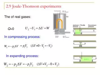
Schematic Layout of the Flow Setup and the proposed Cryogenic System [1: proposed cryo cold head, 2: common compressor for the JT cryogenic system, 3: common heat exchanger for external heat rejection, 4: recuperative heat exchanger for regeneration, 5: JT expansion valve – this would be located physically next to item 6, 6: cold head heat exchanger, 7: vacuum jacket, dark arrows indicate flow of neon, open arrows indicate flow of LN2]
Qrej External HX JT expander Motor and Compressor Recuperator Load Interface Cold head JT Cryocooling System
Schematic representation of Joule-Thomson Cycle with respect to the current system
Specifications • Compressor: • Pressure Ratio = 10, Efficiency = 85%, • Working Fluid = Neon, Operating pressure range = 3 bar to 30 bar, • Electric Power required to run the motor for compressor = 12 kW. • Recuperative Heat Exchanger: • Temperature drop/rise = 227 K, • Pressure difference between Hot side and Cold side = 27 bar. • JT Valve: • JT coefficient = 0.259, Temperature drop across JT Valve = 7 K. • Heat Sink: • Heat Load = 2196 W, Working pressure = 30 bar. • Cold Head: • Cooling power = 20 W, Working pressure = 3 bar. • Overall system: • Working Fluid = Neon, Working pressure range = 3 bar to 30 bar, • Mass flow rate/cold head = 3.953 g/s, • System COP = 0.0078.
Other considerations and Optimization • Lowering of the inlet temperature to the compressor from 300 K to 280 K No use. Instead it lowers the COP value. • Increasing Pressure Ratio to 70 (operating pressure range of 1 bar to 70 bar) Improves COP and JT coefficient. But the option is discarded owing to the difficulty in designing the miniature heat exchanger for a pressure difference of 69 bar.
Companies contacted for purchase of off-the-shelf Compressorand JT Valve • Fluitron, Inc. – negotiation in active progress. • RIX Industries – negotiation in active progress. • Sundyne Corp., • Gas Equipment Engg. Corp.(GEECO), • Burton Corblin, Inc. • ProcessFlo, Inc. • Hydro-Pac Inc. – negotiation in active progress. • CPC-Cryolab(tm) – negotiation in active progress.
Future Work • To accomplish Task II: Development and Fabrication of a Highly Effective, Compact Recuperative Heat Exchanger. • NOTE:Cycle specifications are optimized based on the fact that LN2 test bed would be used for conducting the experiment.