Download
1 / 43
520 likes | 902 Views
Computer Buses. For many of you who have depopulated his/her breadboards, THANKS! There are still some to be depopulated. Please don’t forget to do it this week, please. Final Exam – Thur, Dec 11, 4:15-6:20.

E N D
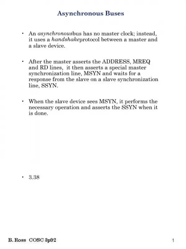
Computer Buses For many of you who have depopulated his/her breadboards,THANKS! There are still some to be depopulated. Please don’t forget to do it this week, please.
Final Exam – Thur, Dec 11, 4:15-6:20 • Logic, Flip Flops, Timing, Synchronous / Asynchronous Circuits, Memory Organization, Finite State Machines (FSM) • RISC / CISC Computers, MIPS Organization, MIPS Instructions, MIPS Addressing, MIPS Frames / Context Switching, MIPS Assembly/Machine Programming (will have MIPS card) • Hamming Code • Developing MIPS Datapaths, MIPS FSM Implementations, and Alternative Microprogramming Midterm ---------------------------------- • Pipelining - implementing, forwarding, handling branches • Cache – Direct, Associative, Set Associative • Virtual memory – Organization, Page Faults, and Look Aside Buffer • IA-64 - Bundled Instructions /explicit parallel, predicated execution, control speculation, speculative data loading, software pipelining / unraveling loops (don’t expect you to know details of the IA-64) • I/O Devices & Buses – Magnetic Disks, Solid State Disks, Flash Memory, Optical Disks, Magnetic Tape - Organization, Implementation, Interrupts, Bus Control, DMA 60% on material covered after the midterm
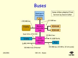
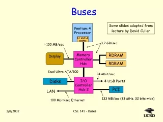
I/O Controller I/O Controller … … Disk Disk Disk Disk Basic I/O System Example Processor Cache Memory - I/O Bus Main Memory
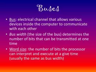
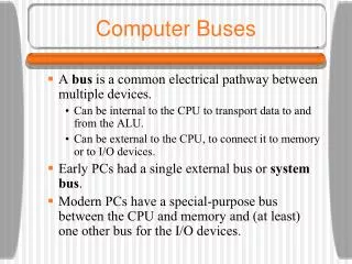
Computer Buses • The bus is a critical component of the Computer: • They are shared components that provide the paths for all parts of the computer to communicate with each other • They can reduce the complexity of communications between computer components • They contain conduits for data, “addressing”, and timing/control • They need a protocol that all users use • They can provide an easy way to evolve a computer system – add components • They can be a serious bottleneck if not designed and used appropriately • As systems grow, they need to evolve hierarchically • They can be parallel or serial • They can have data widths larger than the computer word length
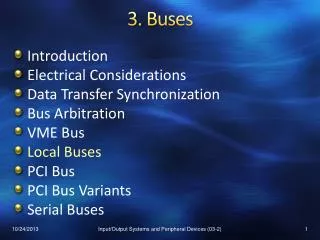
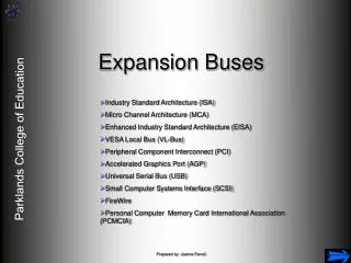
Types of Buses • Processor-memory bus (maybe proprietary) • Short and high speed • Matched to the memory system to maximize the memory-processor bandwidth • Optimized for cache block transfers • Backplane bus (maybe industry standard) • The backplane is an interconnection structure within the chassis • Used as an intermediary bus connecting I/O busses to the processor-memory bus • I/O bus (industry standard, e.g., SCSI, PCI,USB, Firewire) • Usually is lengthy and slower • Needs to accommodate a wide range of I/O devices • Connects to the processor-memory bus or backplane bus
Bus Characteristics Control lines: Master initiates requests • Data & Address lines • Data, addresses, and complex commands • Control lines • Signal requests and acknowledgments • Indicate what type of information is on the data lines • Bus transaction consists of • Master issuing the command (and address) – request • Slave receiving (or sending) the data – action • Defined by what the transaction does to memory • Input – inputs data from the I/O device to the memory • Output – outputs data from the memory to the I/O device Bus Master Bus Slave Data lines: Data can go either way
Buses • What are the Bus design considerations? • Accessibility • Speed • Reliability • Extensibility • Bottle necks • Noise (electrical) • Flexibility • Ease of Interfacing • Power • Sharability • Communication Protocol • Length Should Buses distribute Power?
Computer Bus Buses are composed of three sets of lines Not all devices will use all lines in each category
Computer Bus Control lines include: Clock(s) Interrupt Support Bus Control R/W etc.
Bus Communications • Bus Protocols • Asynchronous • Synchronous • Memory Read / Writes ? • I/O Read Writes? • Peer communication – e.g. CPU to CPU • Are communications verified? • Is there error checking ?
Synchronous and Asynchronous Buses • Synchronous bus (e.g., processor-memory buses) • Includes a clock in the control lines and has a fixed protocol for communication that is relative to the clock • Advantage: involves very little logic and can run very fast • Disadvantages: • Every device communicating on the bus must use same clock rate • To avoid clock skew, they cannot be long if they are fast • Asynchronous bus (e.g., I/O buses) • It is not clocked, so requires a handshaking protocol and additional control lines (ReadReq, Ack, DataRdy) • Advantages: • Can accommodate a wide range of devices and device speeds • Can be lengthened without worrying about clock skew or synchronization problems • Disadvantage: slow(er)
ReadReq 1 2 addr data Data 3 4 Ack 6 5 7 DataRdy Asynchronous Bus Handshaking Protocol • Output (read) data from memory to an I/O device • I/O device sees DataRdy go low and drops Ack I/O device signals a request by raising ReadReq and putting the addr on the data lines • Memory sees ReadReq, reads addr from data lines, and raises Ack • I/O device sees Ack and releases the ReadReq and data lines • Memory sees ReadReq go low and drops Ack • When memory has data ready, it places it on data lines and raises DataRdy • I/O device sees DataRdy, reads the data from data lines, and raises Ack • Memory sees Ack, releases the data lines, and drops DataRdy
Physical Considerations • How are the various components connected? • Unidirectional / bidirectional • And /Or combinational circuits • Wired Or circuits • Tri-state
Or configuration: Normal Gate Output Stage: Observe that the output is always driven High or low. What happens if we connect two of these to the bus?
Wired OR Now any new device can just be connected to the bus anywhere. If no device is pulling the bus line low, it is high A NOR function
Tri-State Now each device can either drive the line high, drive it low, or leave it open
Symbols Buffer Open Collector Tri-State
Signal Considerations • What about signal integrity? • Fanout • What about noise? • Drivers • What about length limitations? • Bus termination
Characteristic Impedance Terminated at Char Impedance Not Terminated at Char Impedance
Termination comparisons Open Termination Short Termination Proper Termination
A Typical I/O System Interrupts Processor Cache Memory - I/O Bus Main Memory I/O Controller I/O Controller I/O Controller Graphics Network Disk Disk
Interrupt Systems • Interrupt Systems Allow Devices to request I/O Service when THEY are ready • Process? • Device given “permission” to generate an Interrupt Request • Request an Interrupt of the present process (IF priority allows) • On Request Acknowledge, provide “Vector” of Service Routine (just like a memory read) • CPU makes a context switch and begins the Service Routine • On completion of the service, a context switchback occurs • The original process continues where it left off
Bus Master • A bus Master controls the bus • Reads • Writes • Interrupt Request / Acknowledge • Bus Master Request / Acknowledge • Why would there be multiple potential Bus Masters? • Multiple Processor Shared Systems • One Processor can use the bus while another is doing internal processing • To accommodate the replacement of a “bad” bus master • Sometimes there is a voting system to determine Bus Control • Allows I/O devices to talk to memory or another I/O Device without using the processor time
Bus Master • How does a Bus Master System work? • A potential Bus Master can Request the Bus Control • On Acknowledgement / Grant the new Master Takes Control • When there is a timeout due to no bus activity • A Potential Bus Controller announces intention to take control • Unless there is an objection, it then takes Control • If there are multiple requests • There is an arbitration process to determine who takes control
DMA (Direct memory Access) • Is there some way to use the bus when the master is not using it? • Yes, its called a DMA • To use the Bus, a device must request to DMA • On Grant, the device can make multiple transfers and then give up the Bus. During this time the Bus Master doesn’t use the Bus (possibly goes to sleep) • How is it used? • Typically, a device, like a Disk, requests the right to DMA one word or a Block of Words to a memory “page”. • When granted, the Disk fills the Block – in a burst (while the Bus Master perhaps sleeps) or one word at a time when the bus is not busy. • When the Block has been transferred, the Device may likely Interrupt the CPU to report the transaction is completed.
The Need for Bus Arbitration • Multiple devices may need to use the bus at the same time so must have a way to arbitrate multiple requests • Bus arbitration schemes usually try to balance: • Bus priority – the highest priority device should be serviced first • Fairness – even the lowest priority device should never be completely locked out from the bus • Bus arbitration schemes can be divided into four classes • Daisy chain arbitration – see next slide • Centralized, parallel arbitration – see next-next slide • Distributed arbitration by self-selection – each device wanting the bus places a code indicating its identity on the bus • Distributed arbitration by collision detection – device uses the bus when its not busy and if a collision happens (because some other device also decides to use the bus) then the device tries again later (Ethernet)
Daisy Chain Bus Arbitration • Advantage: simple • Disadvantages: • Cannot assure fairness – a low-priority device may be locked out indefinitely • Slower – the daisy chain grant signal limits the bus speed Device 1 Highest Priority Device N Lowest Priority Device 2 Ack Ack Ack Release Bus Arbiter Request wired-OR Data/Addr
Centralized Parallel Arbitration • Advantages: flexible, can assure fairness • Disadvantages: more complicated arbiter hardware • Used in essentially all processor-memory buses and in high-speed I/O buses Device 1 Device 2 Device N Request1 Request2 RequestN Ack1 Ack2 Bus Arbiter AckN Data/Addr
Layering – Example: OSI Network Layers International Standards Organization’s (ISO) Open Systems Interconnection (ISO) Model: • The Physical Layer describes the physical properties of the various communications media, as well as the electrical properties and interpretation of the exchanged signals. • Example: this layer defines the size of Ethernet coaxial cable, the type of BNC connector used, and the termination method. • The Data Link Layer describes the logical organization of data bits transmitted on a particular medium. • Example: this layer defines the framing, addressing and check-summing of Ethernet packets. • The Network Layer describes how a series of exchanges over various data links can deliver data between any two nodes in a network. • Example: this layer defines the addressing and routing structure of the Internet. • The Transport Layer describes the quality and nature of the data delivery. • Example: this layer defines if and how retransmissions will be used to ensure data delivery. • The Session Layer describes the organization of data sequences larger than the packets handled by lower layers. • Example: this layer describes how request and reply packets are paired in a remote procedure call. • The Presentation Layer describes the syntax of data being transferred. • Example: this layer describes how floating point numbers can be exchanged between hosts with different math formats. • The Application Layer describes how real work actually gets done. • Example: this layer would implement file system operations.
Simple Example OF 7 Layer OSI Model Application Layer: Set of C Instructions, Set of Data {I0 I1 I2 …. IN Do D1 D2 … Dm} Presentation Layer: ASCII Coding {ASC{I0 I1 I2 …. IN Do D1 D2 … Dm}} Session Layer: What process at computer x is communicating with what process at computer y {X4 Y6{ASC{I0 I1 I2 …. IN Do D1 D2 … Dm}}} Transport Layer: Guaranteed Transmission, sequentially numbered packets of 4096 bytes {GT4 P34{X4 Y6{ASC{I0 I1 I2 …. IN Do D1 D2 … Dm}}}PCKSUM} Network Layer: Path through Network {N23 N3 N53{GT4 P34{X4 Y6{ASC{I0 I1 I2 …. IN Do D1 D2 … Dm}}}PCKSUM}} Data Link Layer: Serial 256 bytes per frame {STRTT{N23 N3 N53{GT4 P34{X4 Y6{ASC{I0 I1 I2 …. IN Do D1 D2 … Dm}}}PCKSUM}}CHKSM} Physical Layer: 9600Baud, Coax cable - {Start {….}Parity Stop Stop}