Download
1 / 30
300 likes | 399 Views
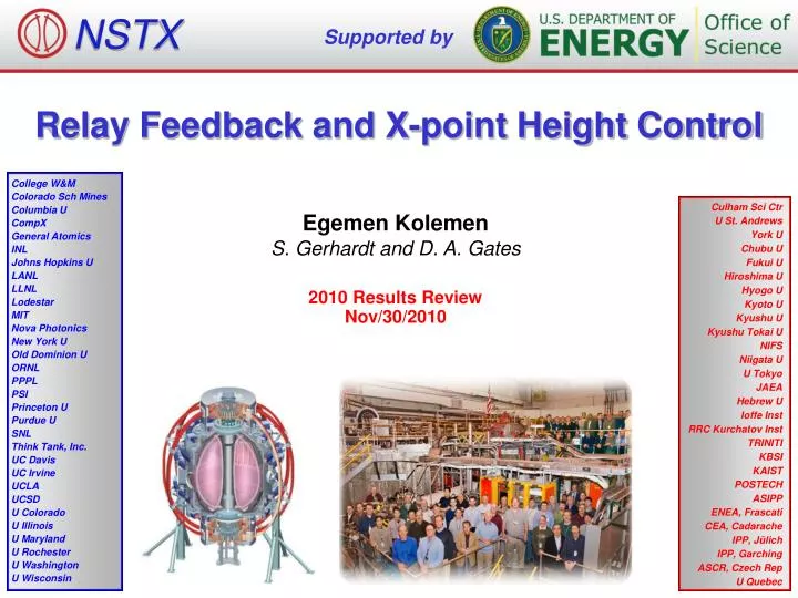
NSTX. Supported by . Relay Feedback and X-poin t Height Control. College W&M Colorado Sch Mines Columbia U CompX General Atomics INL Johns Hopkins U LANL LLNL Lodestar MIT Nova Photonics New York U Old Dominion U ORNL PPPL PSI Princeton U Purdue U SNL Think Tank, Inc.

E N D
NSTX Supported by Relay Feedback and X-point Height Control College W&M Colorado Sch Mines Columbia U CompX General Atomics INL Johns Hopkins U LANL LLNL Lodestar MIT Nova Photonics New York U Old Dominion U ORNL PPPL PSI Princeton U Purdue U SNL Think Tank, Inc. UC Davis UC Irvine UCLA UCSD U Colorado U Illinois U Maryland U Rochester U Washington U Wisconsin Culham Sci Ctr U St. Andrews York U Chubu U Fukui U Hiroshima U Hyogo U Kyoto U Kyushu U Kyushu Tokai U NIFS Niigata U U Tokyo JAEA Hebrew U Ioffe Inst RRC Kurchatov Inst TRINITI KBSI KAIST POSTECH ASIPP ENEA, Frascati CEA, Cadarache IPP, Jülich IPP, Garching ASCR, Czech Rep U Quebec Egemen Kolemen S. Gerhardt and D. A. Gates 2010 Results Review Nov/30/2010
2009 Run:Experimental System ID (Open Loop) P • System Id: Identify the effect of the actuator on the boundary shape. • Reaction Curve Method • From Step Response obtain: • Time delay, rise time and size of change gives the control tuning parameters. Time
2009 Run: Experimental System ID (Open Loop) P • System Id: Identify the effect of the actuator on the boundary shape. • Reaction Curve Method • Problem: • Many shots needed • Need the actuator in open loop. • Not precise System Id results from 2009 run
Experimental System ID: Closed Loop Auto-tune with Relay Feedback • Advantages: • Only a single experiment is needed. • Closed loop: • More stable • Enable system ID for actuators that can’t be open loop (for example: vertical control) Control Output • The closed-loop plant response period (Pu) & amplitude (A) are used for PID controller tuning. Process Output
Experimental System ID: Closed Loop Auto-tune with Relay Feedback • Advantages: • Only a single experiment is needed. • Closed loop: • More stable • Enable system ID for actuators that can’t be open loop (for example: vertical control) Control Output • The closed-loop plant response period (Pu) & amplitude (A) are used for PID controller tuning. Process Output A h Pu
Successful Developed Combined X-point Height / SP Control • Tuned via Relay-Feedback. • Achieved RMS <1 cm X-point height error and <2 cm SP. • Scenario used for LLD experiments. Evolution of Plasma Boundary: X-point height roughly constant as OSP ramps
For 2011: Solution to “Hand-off” Problem • Problem when changing between control phases. • Normal Control has two parts: • Trajectory control: Scenario Development (Feed forward) • Feedback control: Controlling parameters close to the defined scenario. • Need: Ability to add these two waveforms. • Simply be able to add PID output to the Voltage from the last phase. (We have this capability only for Relay Feedback but not for regular PID). • Then, we will avoid “hand-off” problem
NSTX Supported by Squareness XP College W&M Colorado Sch Mines Columbia U CompX General Atomics INL Johns Hopkins U LANL LLNL Lodestar MIT Nova Photonics New York U Old Dominion U ORNL PPPL PSI Princeton U Purdue U SNL Think Tank, Inc. UC Davis UC Irvine UCLA UCSD U Colorado U Illinois U Maryland U Rochester U Washington U Wisconsin Culham Sci Ctr U St. Andrews York U Chubu U Fukui U Hiroshima U Hyogo U Kyoto U Kyushu U Kyushu Tokai U NIFS Niigata U U Tokyo JAEA Hebrew U Ioffe Inst RRC Kurchatov Inst TRINITI KBSI KAIST POSTECH ASIPP ENEA, Frascati CEA, Cadarache IPP, Jülich IPP, Garching ASCR, Czech Rep U Quebec Egemen Kolemen S. Gerhardt and D. A. Gates 2010 Results Review Nov/30/2010
First Ever Use of PF4 for Shape Optimization • Motivation 1: Increased current capability of NSTX Upgrade may require vertical field from the PF4 in addition to PF5. • Preprogram PF4 with PF5 for outer gap control Pos. PF4 PF5 PF4 Neg. PF4 Without PF4
Squareness, ζ, Control with PF4 • Motivation: Assess the physics impact of squareness variation while other shape parameters are fixed. • PF4 best ζ control candidate. PF3/PF4 effect ζ but PF3 used for vertical stability. • Achieved stable ζ tracking via PF4. • Effect of ζ on plasma is being studied. Pos. PF4 PF5 PF4 Neg. PF4 Without PF4
XMP Control Results: PF3-PF4 interaction • To solve this problem, move the PF3 and PF4 control segment. • Could not do this: • Problem with PCS Segment Editor. • Hopefully will be fixed for 2011. • To overcome the problem without changing the segments: • Hand adjust a non-realistic looking shape request. • Squareness Request of +0.4 from the normal request. • Works but don’t use the squareness in these shots.
Pressure Profile Change as PF4 Increases PF4= 0, 1, 4, 6,8 • PF4 (opposing PF5) up to 5 kA (~2 inches in figure) increases pressure • Too high PF4 interacts with the wall and plasma is not as good.
Higher Performance: PF4 of 1-4 kA • Optimal PF4 ~1-4 kA for performance. • Confinement time increases • Energy confinement increases • Flux consumption reduces. • Too high PF4 interacts with the wall and plasma is not as good. • Note for comparison: • Negative squareness results were all worse than PF4=0 fiducial case. [142353,142342,142343,142347,142348]
PF4 at 8 kA, High Squareness Each Line is 1 cm apart • As PF4 gets close to 8 kA: • Last closed flux surface gets 3-4 cm close to the wall. • Pressure profile degrades PF4= 0, 1, 4, 6,8
NSTX Supported by Vertical Stability for NSTX and NSTX-U Egemen Kolemen D. A. Gates, S. Gerhardt College W&M Colorado Sch Mines Columbia U CompX General Atomics INL Johns Hopkins U LANL LLNL Lodestar MIT Nova Photonics New York U Old Dominion U ORNL PPPL PSI Princeton U Purdue U SNL Think Tank, Inc. UC Davis UC Irvine UCLA UCSD U Colorado U Illinois U Maryland U Rochester U Washington U Wisconsin Culham Sci Ctr U St. Andrews York U Chubu U Fukui U Hiroshima U Hyogo U Kyoto U Kyushu U Kyushu Tokai U NIFS Niigata U U Tokyo JAEA Hebrew U Ioffe Inst RRC Kurchatov Inst TRINITI KBSI KAIST POSTECH ASIPP ENEA, Frascati CEA, Cadarache IPP, Jülich IPP, Garching ASCR, Czech Rep U Quebec Monday Physics Meeting PPPL, NJ Nov/15/2010
2008 Run: Vertical Displacement Measurements • At 300 ms, we turned the controller off and let the plasma drift. • When we turned the control back on some of the shots recovered while others hit the wall. Vertical displacement for controllable shots (Cut off at the point of return) Vertical displacement for uncontrollable shots
Vertical Displacement Measurements • At 300 ms, we turned the controller off and let the plasma drift. • When we turned the control back on some of the shots recovered while others hit the wall. Vertical displacement for controllable shots (Cut off at the point of return) Vertical displacement for uncontrollable shots
Toksys Results Growth Rate (Gamma) 20-25 s^-1 Shot # Gamma s^-1 127077 23 127078 25 127079 24 127080 22 127081 24 127082 22 127083 20 127084 20 127085 21 127086 23 127087 21
Mismatch Between XP and Toksys • XP data more unstable (3-4 times) than the model Example of a mismatch between TokSys numerical plasma model and the experimental data. Depending on how the model is used plasma or te coil model.
All XPs Can Be Modeled with the Same Two Parameters x x • Where =75s-1. The first order effect of the coils on the vertical motion is assumed to be: • i.e. the current changes the velocity of the rigidly moving plasma. Also during the ramp up I is proportional to t. Combining these two effects, we can find an approximation for the dynamics of the vertical motion after the control is turned on as: • is found by data fitting as 4.5e5
2010 Experiment: High Aspect Ratio Vertical Growth Rate • Thanks to Relay Feedback, we were able to freeze voltage request in Isoflux for the first time. • This enabled vertical growth rate measurements
New Experimental Growth Rate (Gamma) 45-170 s^-1 • versus 10-42 s^-1 for Model • High Aspect Ratio More Unstable • Need better vertical control for Upgrade • Trying to fix the TokSys model • Also, trying to update the Power Supply model (with R. Hatcher) • Probably need better models (3D?). RED: Data, BLUE: Model
Slide title • Important main point • Important detail • Another important sub-detail
First Ever Use of PF4 for Shape Optimization • Ramp PF4 to 7 kA • PF1A decreased to give the same kappa. • PF5 decreases as PF4 increases. • Squareness decreases. • Keep other things the same.
XMP Control Results: PF3-PF4 interaction • With PF4 control on, we reduced the gain for PF3 %30 at 360 ms. • PF4 compensated for the loss of inward pushing effect of PF3. • PF4 can offset both PF3 and PF5.
XMP Control Results: PF3-PF4 interaction • Figure show the result of a ramp on PF4 from 0 to 2.6 kA. • As PF4 increases, squareness change. • In order to align, PF3/4/5 control points (shown in dashed black, dashed red and blue) X-point moves down. • To solve this problem, move the PF3 and PF4 control segment. Shown in solid red, black. • Could not do this: • Problem with PCS Segment Editor. • Hopefully will be fixed for 2011.
Higher Performance: PF4 of 1-4 kA PF4= 0, 1, 4, 6,8 • Optimal PF4 ~1-4 kA for performance. • Confinement time increases • Energy confinement increases • Flux consumption reduces. • Too high PF4 interacts with the wall and plasma is not as good. [142353,142342,142343,142347,142348]
Lower BetaN Limit for PF4 in the positive direction No PF4 5 MW till 450 ms 5 MW till 300 ms