Download
1 / 28
280 likes | 420 Views
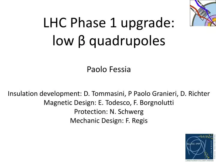
LHC Phase 1 upgrade: low β quadrupoles Paolo Fessia Insulation development: D. Tommasini, P Paolo Granieri, D. Richter Magnetic Design: E. Todesco, F. Borgnolutti Protection: N. Schwerg Mechanic Design: F. Regis. Summary. Approach to the problem and original planning The starting blocks

E N D
LHC Phase 1 upgrade:low βquadrupolesPaolo FessiaInsulation development: D. Tommasini, P Paolo Granieri, D. RichterMagnetic Design: E. Todesco, F. BorgnoluttiProtection: N. SchwergMechanic Design: F. Regis
Summary • Approach to the problem and original planning • The starting blocks • The development of a new porous insulation and other efforts to be able to cope with thermal load • The conceptual magnetic design • The conceptual mechanical design • The resulting coccept
The Approach to the problem • Guide-lines • Maximum use of material and components that have been purchased for the LHC construction, but not used • (this taking into account that we need to keep safety margins for the LHC exploitation). • Use of existing tooling that canbe modified, but in such a way to be fully operational for the original use (if needed for LHC). • Exploitation of LHC magnets used and proved techniques, possibly limiting R&D efforts and reducing technological risks
Magnet program planning as set in February 2008 After ¾ incident delayed of 6 months at least
AT PH
Development of new porous insulation topology: aim Third layer 1 tape 9 mm wide 69 µm thick and 1 mm space • Provide adequate electrical insulation • Increase the heat removal in order to better cope with the energy deposited by the I.P. debris • E-modulus should be not be too much reduced and the coil should be creep stable • Suitable to be industrialized: • Commercially available material • Use of Dipole recovered insulating machine 50 µm Second layer 1 tape 3 mm wide 50 or 75 µm thick and 1.5 mm space
MQXC cross sections and iron yoke with heat exchanger(s) Two possible solutions for heat exchanger proposed by the cryogenic team: 2 heat exchanger in parallel inner diameter 71 mm (1steval. wall thickness 2.5 mm). Hole diameter 80 mm 1 heat exchanger inner diameter 100 mm (1steval. wall thickness 3.5 mm). Hole diameter 110 mm Both are large holes in the iron that affect transfer function and field quality We can consider 2 possible configurations Holes along the 2 mid-planes (larger effect on the transfer function) Holes at 45 ⁰ We prefer solution with 1 heat exchanger on the vertical mid plane because of Simpler interconnect Standardization of cold masses respect 1 heat exchanger at 45 ⁰
Effect of a slot in the iron on the magnetic field quality • Odd multipoles are not affected • Only even multipoles b4, b6, b8 and b10 are affected (multipole variation higher than 0.0001 unit) gap MQXC V24
Proposed Coil Cross-Section • Coil blocks features • Angular position of the point 1 & 2 (mechanical requirement: angles < 41º) • Point 1: ~35º • Point 2: ~26º 1 2 MQXC V24 MQXC V24
Iron Yoke Dimensions • Distance between coil outer radius and iron inner radius is of ~ 38.6 mm. • He holes are radialy centered. this lefts about 20 mm of matter on each side. • The small hole (Ø 20.5 mm) is used for the rods. It can be moved somewhere else because its impact on the multipoles is low. 20 mm MQXC V24
Peak field in the head,30 mm of coil more and a lot more of margin in the head 4 2 1
Key layout analysis 24 degrees 15 degrees Forces repartition on keys according to 1key or 2key layout per quadrant structure
Key layout analysis • Coil radial displacement in function of the angular distance between keys
FE analysis – bending effect =120mm I.L.