Download

1 / 31
410 likes | 1.09k Views
Estimation of Losses in Large Turbines. P.M.V. Subbarao Associate Professor. Department of Mechanical Engineering Indian Institute of Technology, Delhi. Accounting of Losses is Saving of Losses……. Sequence of Energy Losses. Steam Thermal Power. Blade kinetic Power. Steam kinetic

E N D
Estimation of Losses in Large Turbines P.M.V. Subbarao Associate Professor Department of Mechanical Engineering Indian Institute of Technology, Delhi Accounting of Losses is Saving of Losses……
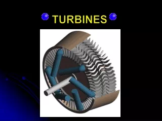
Sequence of Energy Losses Steam Thermal Power Blade kinetic Power Steam kinetic Power Nozzle Losses Stage Losses Moving Blade Losses Isentropic efficiency of Nozzle Blade Friction Factor
Losses in Turbine Stage • Losses in Regulating valves : The magnitude of loss of pressure due to throttling with the regulating valves fully open is: • Dpv = 3 to 5% of pmax. • Loss in nozzle blades. • pressure loss in moving blades. • Loss due to exit velocity. • Loss due to friction of the disc and blade banding • Loss associated with partial admission. • Loss due to steam leakages through clearances. • Loss due to flow of wet steam. • Loss due to exhaust piping. • Loss due to steam leakage in seals.
Losses in Nozzles • Losses of kinetic energy of steam while flowing through nozzles or guide blade passages are caused because of • Energy losses of steam before entering the nozzles, • Frictional resistance of the nozzles walls, • Viscous friction between steam molecules, • Deflection of the flow, • Growth of boundary layer, • Turbulence in the Wake and • Losses at the roof and floor of the nozzles. • These losses are accounted by the velocity coefficient, f.
Loss in nozzle cascade, kJ/kg Theoretical steam velocity at nozzle exit, m/s. Loss in moving blade cascade, kJ/kg • Relative steam velocity at entry to moving blade cascade, m/s Exit velocity Energy kJ/kg Absolute velocity at moving blade exit, m/s.
Available energy of stage, kJ/kg Blade efficiency,
HP Turbine per stage Enthalpy drop profiles at designed condition.
Nozzle& Moving Blade Losses for HP Stages at Designed condition
IP Turbine per stage Enthalpy drop profiles at designed condition.
Nozzle& Moving Blade Losses for IP Stages at Designed condition
LP Turbine per stage Enthalpy drop profiles at designed condition.
Nozzle& Moving Blade Losses for LP Stages at Designed condition
Gland leakage losses The steam leaked out from the system does not work on the blades, it represents energy loss 1.Diaphragm leakage It takes place in stages through the radial clearance between the stationary nozzle diaphragm and the shaft or drum. 2.Tip leakage It occurs in stages through the clearance between the outer periphery of the moving blades and the casing due to the pressure difference existing across the blade. 3.Shaft leakage • Shaft leakage occurs through radial clearance between the shaft and casing at both high and low pressure ends of turbines. • At the high pressure end , steam leaks out to the atmosphere, whereas at the LP end, the pressure being less than the atmospheric , air leaks into the shell
Loss by leakage through diaphragm gland, Loss by leakage through banding gland,
Turning loss These occurs as the steam turns in the blade passage. Disc friction loss • When the turbine disc rotates in the viscous steam, there is surface friction loss due to relative motion between the disc and steam particles. Due to centrifugal force , steam thrown radially outward. • The moving disc exerts a drag on the steam, sets it in motion from root to tip, and produces a definite circulation. • Some part of Kinetic energy of steam is lost due to this friction.
Friction loss, Relative Internal efficiency, Effective enthalpy drop, Power of the stage,
Losses associated with partial admission of steam • Partial admission of steam to turbine stages is employed in cases when the volume flow rate of steam is not high (ie. Turbine of low capacity) • In turbine with partial admission ,steam is fed onto the moving blades only an arc of length , rather than along the entire circumference. • Along the arc , there is no active flow of steam , and the blade passage opposing this arc are filled with stagnant steam from the disc chamber. • Owing to the rotation of the disc , the steam filling this passage is entrained by centrifugal force and moves from the roots to tips of moving blade;
Steam can even flow from one side of the blade to the opposite side Diagram of windage currents in a partial admission turbine stages • The work associated with this motion of the steam in blade passages of the inactive portion of the arc of moving blades, is lost- • Usual energy of the turbine stage is decreased by the energy loss associated wit this motion ( windage) of steam in blade passages
Residual velocity loss Steam leaving the last stage of the turbine has certain velocity, which represent the amount of kinetic energy that cannot be imparted to the turbine shaft and thus it is wasted Exhaust end loss Exhaust end loss occur between the last stage of low pressure turbine and condenser inlet. 2. Exhaust loss depends on the absolute steam velocity. Turbine Exhaust end loss = Expansion-line -end point - Used energy end point.
Typical exhaust loss curve : Annulus restriction loss Annulus velocity (m/sec) SP.Volume Total Exhaust Loss 50 Condenser flow rate Turn-up loss 40 Gross hood loss Annulus area Exhaust Loss of dry flow 30 20 Actual leaving loss Percentage of Moisture at the Expansion line end point 10 0 120 240 180 240 300 360 Annulus Velocity (m/s)
Problems in Low pressure turbine • In the case of condensing turbines the last few stages operate under wet steam conditions. • This results in the formulation of minute droplets of water. • These droplets under the influence of centrifugal force are thrown out towards the periphery. • At the same time these droplets of water receive an accelerating force from the steam particles in the direction of flow . • Thus some of the kinetic energy of the flowing steam is lost in accelerating these water droplets. • The absolute velocity of the steam is considerably greater than that of the water droplets into the moving blade passages. • The water droplets are deflected onto the back of the moving blades as a result of which the moving blades experience an impact force caused by impingement of the moving blades. • As a result of this moving blades experience an impact force caused by the impingement of water droplets on their backs.
The practical investigations that the blade tips are subjected to wear from one side water droplets present in the last few stages can also result in erosion damage of turbine blades and nozzles . • One of the loss mechanisms in the steam turbine is the kinetic energy of the steam as it leaves the last stage blade. • The lower the kinetic energy, the higher the steam turbine efficiency will be. • The magnitude of loss is proportional to the square of the ratio of the volume flow rate of the steam through the last stage of the steam turbine and the annulus area of the turbine exit. • To decrease the loss, a larger turbine exit annulus area is needed. • An increase in the last stage blade annulus area can be accomplished by either using shorter blades mounted on a larger diameter rotor (larger “hub”) or • by using longer blades mounted on a smaller diameter rotor.
The low-pressure turbine exhaust end is one of the important factors affecting the turbine performance. • The size of the exhaust end is determined by the number of exhaust flows and the length of the last stage blades. • In general, the larger the exhaust ends, the lower the full load net heat rate. Under the part-load conditions. • Turbines with a large exhaust end will deteriorate more rapidly in performance.