Download
1 / 31
590 likes | 1.77k Views
Anti-Aliasing Filter Design. Sampling Process. Analog Signal. Sampling Interval (Ts). Sampled Numbers. Analog-to-Digital Conversion. Analog. Discrete. Digital. Undersampling or Aliasing. Undersampling results in a form of distortion termed as aliasing.

E N D
Sampling Process Analog Signal Sampling Interval (Ts) Sampled Numbers
Analog-to-Digital Conversion Analog Discrete Digital
Undersampling or Aliasing Undersampling results in a form of distortion termed as aliasing. http://www.dsptutor.freeuk.com/aliasing/AliasingDemo.html
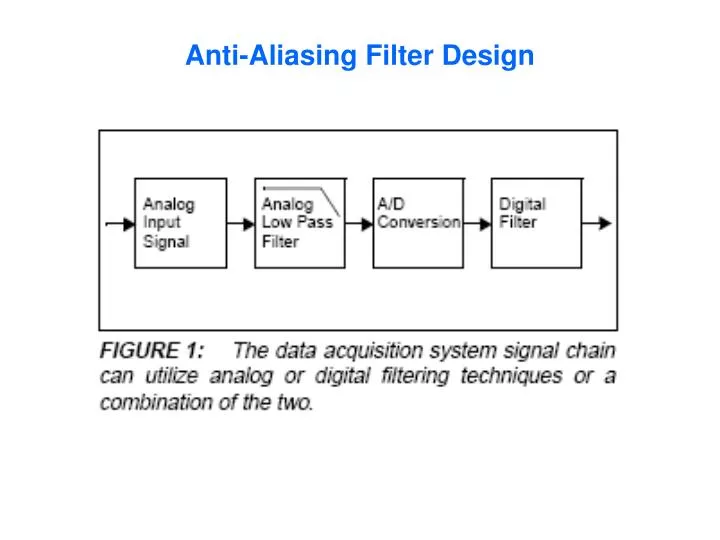
Anti-Aliasing Filter Design Signal of Interest : DC to 1 KHz Analog-to-Digital Converter : 12 bits SAR Sampling Rate : 20 kHz Nyquist Rate : 10 kHz Anti-Aliasing Filter Goal : To filter signals such that high frequency for the analog input do not pass through the A/D Converter.
fsamp fnyq fcutoff Targeted Attenuation Level to prevent aliasing.
fsamp fnyq fcutoff Targeted Attenuation Level to prevent aliasing. 12 bit ADC 212 = 4096 levels Dynamic Range = 20 * log (#levels) 72.3 dB
Anti-Aliasing Filter Design Signal of Interest : DC to 1 KHz Analog-to-Digital Converter : 12 bits SAR Sampling Rate : 20 kHz Nyquist Rate : 10 kHz Anti-Aliasing Filter Goal : To filter signals such that high frequency for the analog input do not pass through the A/D Converter.
Anti-Aliasing Filter Design 5th Order Bessel
Anti-Aliasing Filter Design 3rd Order Chebyshev
Anti-Aliasing Filter Design 4th Order Butterworth
Homework: EEG Amplifier Design Input: 0.1 – 100 Hz Pass-band (switchable to DC-100 Hz) 25 – 100 uV signal levels Differential input CMRR >100 dB Output: Goes to ADC +/- 5 volt Range sampling at 1 kHz rate