Download
1 / 1
10 likes | 104 Views
Combined Fatigue Loading Mode. Basquin curve. Finite life found by plotting alternating and mean Von Mises stresses and drawing a line from the S ut through the plotted point to find σ f at the intersection of the σ alt axis.

E N D
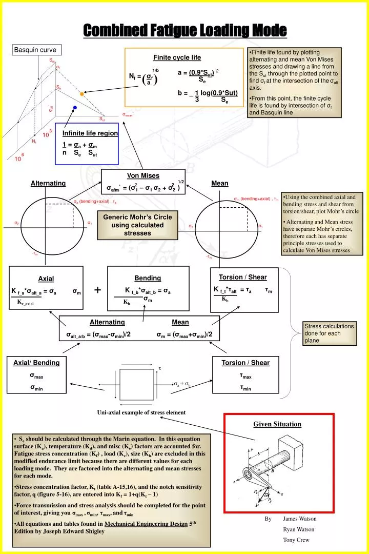
Combined Fatigue Loading Mode Basquin curve • Finite life found by plotting alternating and mean Von Mises stresses and drawing a line from the Sut through the plotted point to find σf at the intersection of theσalt axis. • From this point, the finite cycle life is found by intersection of σf and Basquin line Finite cycle life Sut σf 1/b a = (0.9*Sut) 2 ( ) Nf = σf Se a Se b = _ 1 log(0.9*Sut) 3 Se σalt` σmean` Sut 3 Infinite life region 1 = σa + σm 10 Nf n Se Sut 6 10 Von Mises σa/m` = (σ1 – σ1 σ2 + σ2 ) Alternating 1/2 Mean 2 2 • Using the combined axial and bending stress and shear from torsion/shear, plot Mohr’s circle • Alternating and Mean stress have separate Mohr’s circles, therefore each has separate principle stresses used to calculate Von Mises stresses σm (bending+axial) , τm σa (bending+axial) , τa Generic Mohr’s Circle using calculated stresses σ2 σ1 σ2 σ1 -τm -τm Torsion / Shear K f_t*τalt = τaτm Bending K f_b*σalt_b = σaσm Axial K f_a*σalt_a = σaσm + Kb Kc_axial Kb AlternatingMean σalt_a/b = (σmax-σmin)/2 σm = (σmax+σmin)/2 Stress calculations done for each plane Axial/ Bending σmax σmin Torsion / Shear τmax τmin τ σa + σb Uni-axial example of stress element Given Situation • Se should be calculated through the Marin equation. In this equation surface (Ka), temperature (Kd), and misc (Ke) factors are accounted for. Fatigue stress concentration (Kf) , load (Kc), size (Kb) are excluded in this modified endurance limit because there are different values for each loading mode. They are factored into the alternating and mean stresses for each mode. • Stress concentration factor, Kt (table A-15,16), and the notch sensitivity factor, q (figure 5-16), are entered into Kf = 1+q(Kt – 1) • Force transmission and stress analysis should be completed for the point of interest, giving you σmax ,σmin, τmax,andτmin • All equations and tables found in Mechanical Engineering Design 5th Edition by Joseph Edward Shigley By James Watson Ryan Watson Tony Crew