Download
1 / 27
270 likes | 407 Views
IBL CO 2 c ooling lines installation Review. Didier Laporte CNRS – LPNHE Paris 11 mars 2014. 6. 5. 1. 2. 3. 4. This scenario is about the side A. 7. 8. 2. 3. 4. 5. 1. 6. 7. 8. Guiding support. Support plate. Bottom of the splitter box.

E N D
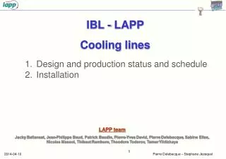
IBL CO2cooling lines installationReview Didier Laporte CNRS – LPNHE Paris11 mars 2014
6 5 1 2 3 4 • This scenario is about the side A 7 8 2 3 4 5 1 6 7 8
Guiding support Support plate Bottomof the splitter box Place and fasten the splitting box on the welding stand
PP1 welding area Position block Intlet-outletjunction Femalefitting
Place the isolator/fitting assembly and Tighten by hand the fitting nut on to the corresponding fake female fitting
Place the first f18mm flexible line and fastenit on the splitting box
A1 liquidline Weld the lowerconnection
Weld the upperconnection A1 liquidline
A1 line completed Transfer to the installation tool
Close the tooling with the cover and lock it The tooling is ready for the installation
LPSC table Ready to receive 8 linestool
Shift the assemblyuntil the splitting box back face touch the plate
And after • Sameoperations for 6 linesside A • Sameoperations for 8 linessideC • Sameoperations for 6 linesside C
Planning • Welding stand, • Installation tooling, • Z table, • Main frame Delivery 18/03/2014