Download
1 / 25
280 likes | 650 Views
Lecture 4. OUTLINE PN Junction Diodes Electrostatics Capacitance I/V Reverse Breakdown Large and Small signal models Reading: Chapter 2.2-2.3,3.2-3.4. Energy Band Description. PN Junction under Reverse Bias .

E N D
Lecture 4 OUTLINE • PN Junction Diodes • Electrostatics • Capacitance • I/V • Reverse Breakdown • Large and Small signal models Reading: Chapter 2.2-2.3,3.2-3.4
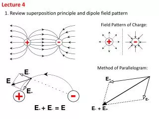
PN Junction under Reverse Bias • A reverse bias increases the potential drop across the junction. As a result, the magnitude of the electric field in the depletion region increases and the width of the depletion region widens.
Mathematical description of current flow in a p-n junction diode
Minority Carrier Injection under Forward Bias • The potential barrier to carrier diffusion is decreased by a forward bias; thus, carriers diffuse across the junction. • The carriers which diffuse across the junction become minority carriers in the quasi-neutral regions; they recombine with majority carriers, “dying out” with distance. np(x) np0 x' edge of depletion region x' 0 Equilbrium concentration of electrons on the P side:
Minority Carrier Concentrations at the Edges of the Depletion Region • The minority-carrier concentrations at the edges of the depletion region are changed by the factor • There is an excess concentration (Dpn, Dnp) of minority carriers in the quasi-neutral regions, under forward bias. • Within the quasi-neutral regions, the excess minority-carrier concentrations decay exponentially with distance from the depletion region, to zero: Notation: Ln electron diffusion length (cm) x'
Diode Current under Forward Bias • The current flowing across the junction is comprised of hole diffusion and electron diffusion components: • Assuming that the diffusion current components are constant within the depletion region (i.e. no recombination occurs in the depletion region):
Current Components under Forward Bias • For a fixed bias voltage, Jtot is constant throughout the diode, but Jn(x) and Jp(x) vary with position. Jtot x -b 0 a
I-V Characteristic of a PN Junction • Current increases exponentially with applied forward bias voltage, and “saturates” at a relatively small negative current level for reverse bias voltages. “Ideal diode” equation:
Practical PN Junctions ID (A) VD (V) • Typically, pn junctions in IC devices are formed by counter-doping. The equations provided in class (and in the textbook) can be readily applied to such diodes if • NA net acceptor doping on p-side (NA-ND)p-side • ND net donor doping on n-side (ND-NA)n-side
Parallel PN Junctions • Since the current flowing across a PN junction is proportional to its cross-sectional area, two identical PN junctions connected in parallel act effectively as a single PN junction with twice the cross-sectional area, hence twice the current.
Diode Saturation Current IS • IS can vary by orders of magnitude, depending on the diode area, semiconductor material, and net dopant concentrations. • typical range of values for Si PN diodes: 10-14 to 10-17 A/mm2 • In an asymmetrically doped PN junction, the term associated with the more heavily doped side is negligible: • If the P side is much more heavily doped, • If the N side is much more heavily doped,
PN Junction under Reverse Bias • A reverse bias increases the potential drop across the junction. As a result, the magnitude of the electric field in the depletion region increases and the width of the depletion region widens.
PN Junction Small-Signal Capacitance • A reverse-biased PN junction can be viewed as a capacitor, for incremental changes in applied voltage.
Voltage-Dependent Capacitance • The depletion width (Wdep) and hence the junction capacitance (Cj) varies with VR. esi 10-12 F/cm is the permittivity of silicon. VD
Reverse-Biased Diode Application • A very important application of a reverse-biased PN junction is in a voltage controlled oscillator (VCO), which uses an LC tank. By changing VR, we can change C, which changes the oscillation frequency.
Reverse Breakdown • As the reverse bias voltage increases, the electric field in the depletion region increases. Eventually, it can become large enough to cause the junction to break down so that a large reverse current flows: breakdown voltage
Reverse Breakdown Mechanisms • Zener breakdown occurs when the electric field is sufficiently high to pull an electron out of a covalent bond (to generate an electron-hole pair). • Avalanche breakdown occurs when electrons and holes gain sufficient kinetic energy (due to acceleration by the E-field) in-between scattering events to cause electron-hole pair generation upon colliding with the lattice.
Constant-Voltage Diode Modelfor Large-Signal Analysis • If VD < VD,on: The diode operates as an open circuit. • If VDVD,on: The diode operates as a constant voltage source with value VD,on.
Example: Diode DC Bias Calculations • This example shows the simplicity provided by a constant-voltage model over an exponential model. • Using an exponential model, iteration is needed to solve for current. Using a constant-voltage model, only linear equations need to be solved.
Small-Signal Analysis • Small-signal analysis is performed at a DC bias point by perturbing the voltage by a small amount and observing the resulting linear current perturbation. • If two points on the I-V curve are very close, the curve in-between these points is well approximated by a straight line:
Diode Model for Small-Signal Analysis • Since there is a linear relationship between the small-signal current and small-signal voltage of a diode, the diode can be viewed as a linear resistor when only small changes in voltage are of interest. Small-Signal Resistance (or Dynamic Resistance)
Small Sinusoidal Analysis • If a sinusoidal voltage with small amplitude is applied in addition to a DC bias voltage, the current is also a sinusoid that varies about the DC bias current value.