Download

1 / 24
260 likes | 545 Views
RC, LR, and LC Circuit Labs. Peggy Bertrand Oak Ridge High School Oak Ridge, TN pbertrand@ortn.edu. College Board Objectives. B. C. RC Circuits. RC Circuit Lab Equipment. Low tech. High tech. Add a Pasco or Vernier system with a voltage probe. Capacitors 100 m F to 300 m F

E N D
RC, LR, and LC Circuit Labs Peggy Bertrand Oak Ridge High School Oak Ridge, TN pbertrand@ortn.edu
RC Circuit Lab Equipment Low tech High tech Add a Pasco or Vernier system with a voltage probe • Capacitors • 100mF to 300 mF • Resistors • 15,000 W or higher • D-Cells • Knife switch (spdt) • Connecting wires • Voltmeter • Kid with a pencil
RC Circuit – low tech $3.00 $5.00 $2.00 <$1.00 $15.00 $1.00
RC Circuit – high tech $3.00 $5.00 $2.00 <$1.00 $350 - $425 $1.00
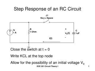
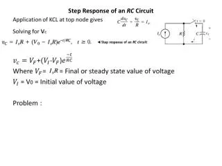
RC Circuit Lab – student instructions Build an RC circuit that can undergo charge and discharge cycles with a flip of the switch. Use capacitors of between 100 mF and 300 mF, and resistors of between 10,000 W and 100,000 W. Collect voltage data over the resistor and over the capacitor for the charge and the discharge cycles and produce graphs of these data. Compare the predicted and graphically determined time constants for your circuit . Repeat for a second circuit with a different capacitive time constant. Your report must include: • Your graphs. • Circuit diagram • Graphically-determined capacitive time constants. • Predicted capacitive time constants. • Comparison of time constant values.
Circuit setup V B A V
RC Circuit Charge and Discharge Data This circuit was built with a 15000 W resistor and a 1000 mF capacitor. Calculated time constant: 15 s. Graphical time constant: 14 s.
LR Circuit Setup A V
LC Circuit Lab Equipment OR AND
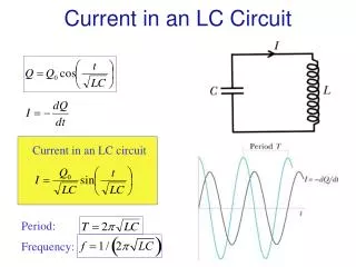
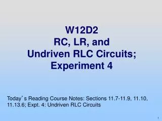
LC Circuit – Instructions to Students • Build an LC circuit with an inductor, capacitor, DC power supply, and a single-pull double-throw switch. • The switch should be used to charge the capacitor using the DC voltage source when it is in one position, and to discharge the capacitor through the inductor when it is in the other position. • There is resistance in your inductor that will damp the oscillations, so don’t add any additional resistance! (You are really building an LRC Circuit) • Rapidly sample the voltage across the capacitor to obtain a damped oscillator curve. • Compare the period you obtain to the predicted period.
Circuit Setup • Capacitor charges when switch is in position A. • When moved to position B, an LRC circuit undergoes damped oscillation with a period predicted by: V A B C e
LC (well, really LRC) Circuit Results Data taken with Pasco Science Workshop 750, sampled at 5000 Hz